
Laser radar and control method of laser radar

A technology of laser radar and control method, applied in the field of optics, can solve the problem that the separation distance is not infinite

Inactive Publication Date: 2020-11-13
锐驰智光(北京)科技有限公司
View PDF5 Cites 1 Cited by
  • Summary
  • Abstract
  • Description
  • Claims
  • Application Information

AI Technical Summary

Problems solved by technology

[0004] However, the distance between the surrounding objects that can be detected by lidar is not infinite. The effective detection distance of lidar for existing self-driving vehicles is about 200 meters

Method used


Image

  • Laser radar and control method of laser radar
  • Laser radar and control method of laser radar
  • Laser radar and control method of laser radar

Examples


no. 1 example

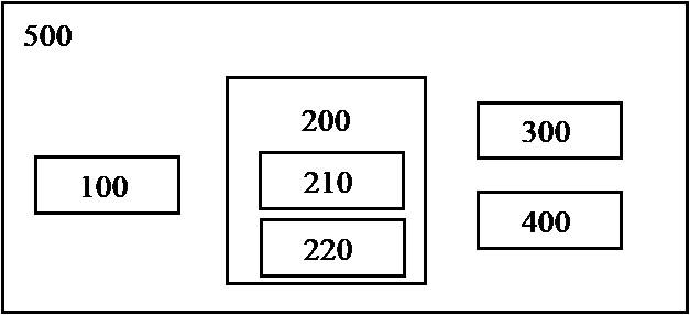
[0027] figure 1 is a schematic diagram showing the laser radar according to the first embodiment of the present invention.

[0028] Such as figure 1 As shown, the lidar of this embodiment includes a casing 500 , a transmitting module 100 , a receiving module 200 , a judging module 300 and a processing module 400 .

[0029] The casing 500 accommodates the transmitting module 100 and the receiving module 200 to protect them from external moisture, dust and the like. Furthermore, the casing 500 has a transmission portion through which the emitted and returned laser beams are transmitted.

[0030] The respective numbers of the transmitting module 100 and the receiving module 200 accommodated in the casing 500 are not limited. One transmitting module 100 and one receiving module 200 can be provided. It is possible to set n transmitting modules 100 and m receiving modules 200 . One transmitting module 100 and n receiving modules 200 may also be provided. It is also possible to...

no. 2 example

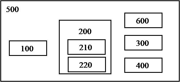
[0068] image 3 is a schematic diagram showing a laser radar according to a second embodiment of the present invention.

[0069] Compared to the lidar according to the first embodiment, the lidar according to the second embodiment may further include an amplifier 600 within the housing 500 .

[0070] The amplifier 600 may be a transimpedance amplifier (TIA), that is, the amplifier 600 may use Ohm's law to convert the output current of the first receiver 210 and / or the second receiver 220 into a voltage and output it as an output voltage .

[0071]The lidar according to the second embodiment of the present invention may include the number of amplifiers 600 corresponding to the first receivers 210 and the second receivers 220 .

[0072] Moreover, the output voltage of the output current of the first receiver 210 converted by the amplifier 600 may be referred to as the output voltage of the first receiver 210, and the output current of the second receiver 220 may be referred to...


PUM


Abstract

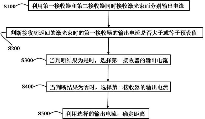
The invention discloses a laser radar and a control method thereof. The laser radar according to an embodiment of the present invention comprises of a transmitting module for transmitting a laser beamto the outside, a receiving module which is used for receiving laser beams which are transmitted from the transmitting module and returned after being reflected by an object outside the laser radar,and comprises a first receiver and a second receiver, a first receiver and a second receiver which are used for simultaneously receiving the returned laser beams and respectively outputting current, and a processing module used for determining the distance between the object and the laser radar by using the output current of the first receiver or determining the distance between the object and thelaser radar by using the output current of the second receiver according to a comparison result of the output current of the first receiver and a preset value when the returned laser beam is received.

Description

technical field [0001] The invention relates to the field of optics, in particular to a laser radar and a control method for the laser radar. Background technique [0002] In the field of autonomous driving, autonomous vehicles can detect surrounding objects with the help of devices such as Lidar (LIDAR). The laser radar emits a laser beam to the surrounding three-dimensional space as a detection signal, and makes the laser beam irradiate the objects in the surrounding space and is reflected to become an echo signal and returns. The laser radar compares the received echo signal with the emitted detection signal. In order to obtain relevant information about surrounding objects such as distance and speed. [0003] The lidar as mentioned above includes a transmitting module and a receiving module. The transmitting module generates and emits a laser beam, and the laser beam that hits the surrounding objects and reflects back is received by the receiving module. Since the s...

Claims


Application Information

Patent Timeline
Patent Type & Authority Applications(China)
IPC IPC(8): G01S17/02G01S7/481
CPCG01S7/481G01S17/02
Inventor 姜波赵忠尧朴光龙
Owner 锐驰智光(北京)科技有限公司
Learn More