
Efficient sedimentation tank used under mine

A high-efficiency sedimentation tank and underground mine technology, applied in sedimentation treatment, flocculation/sedimentation water/sewage treatment, mining wastewater treatment, etc., can solve the problems of high operating cost, large floor area, long process flow, etc., and achieve oxygen utilization The effect of high efficiency, reduced floor area and simple process flow

Pending Publication Date: 2020-11-13
NANJING GUONENG ENVIRONMENTAL PROTECTION ENG
View PDF4 Cites 2 Cited by
  • Summary
  • Abstract
  • Description
  • Claims
  • Application Information

AI Technical Summary

Problems solved by technology

[0003] 1) The traditional treatment process needs to go through preliminary precipitation first, then carry out aeration and oxidation, and remove suspended solids and iron in the water after secondary precipitation. The overall process is too long, the number of equipment and structures is large, and the operating cost is high. ;
[0004] 2) The primary sedimentation tank is required for primary sedimentation, a separate aeration tank is required for aeration and oxidation, and a secondary sedimentation tank is required for secondary sedimentation. The construction of each process section is set up separately, which occupies a large area and the equipment layout is relatively scattered, which is not convenient for operation and management. ;
[0005] 3) A lot of equipment is required, and each process section needs to be equipped with a separate sludge discharge device and flushing device, which is inconvenient to operate;
[0006] 4) There are many structures required, the construction period is long, and it is difficult to dismantle in the later stage

Method used


Image

  • Efficient sedimentation tank used under mine
  • Efficient sedimentation tank used under mine

Examples


Embodiment Construction

[0026] In order to illustrate the present invention more clearly, the following will briefly introduce the drawings used in the implementation cases or the description of the existing invention.

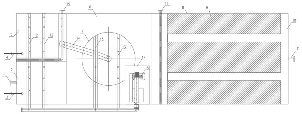
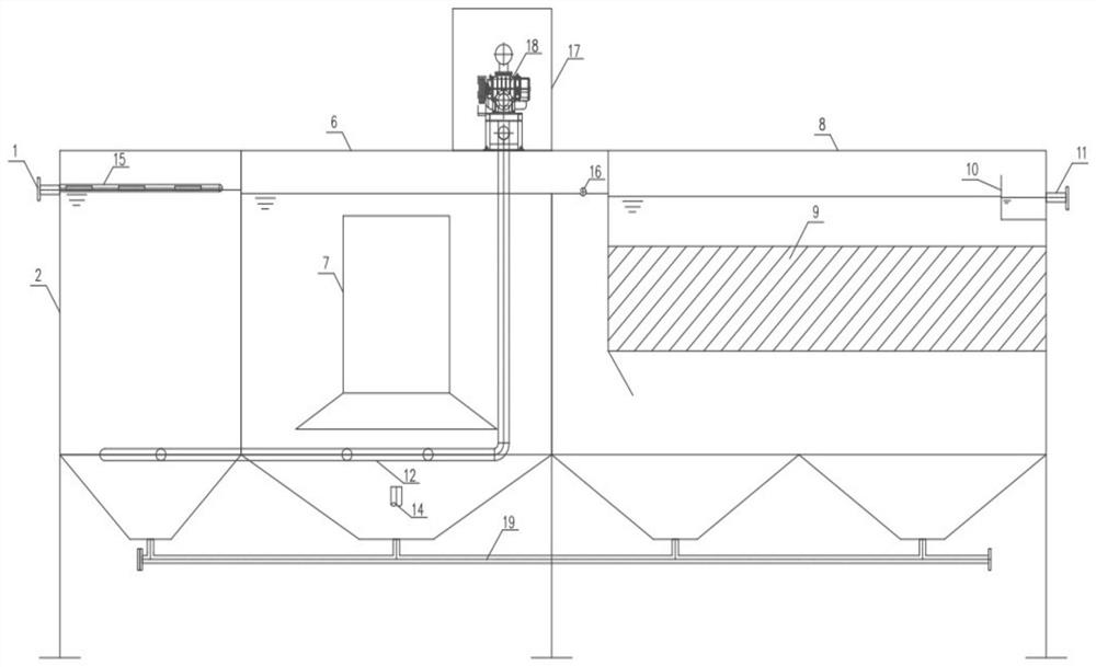
[0027] see figure 1 , is a preferred embodiment of a high-efficiency sedimentation tank for mines, which can treat iron-containing, turbid, and oil-containing wastewater in mines, including mixing area 2, reaction area 5, flocculation area 6, sedimentation area 8, and the second An aeration pipe 12 , a second aeration pipe 13 , an aeration fan 18 , a first oil slick collection pipe 15 , and a second oil slick collection pipe 16 . The details are as follows:

[0028] The mixing zone 2 mainly includes the water inlet 1, the coagulant dosing pipe 3, and the bottom sludge discharge pipe 19, which is mainly used for coagulant dosing and mixing, and the bottom sludge discharge pipe 19 can remove the sludge generated in the mixing zone.

[0029] The reaction zone 5 mainly includes a polya...


PUM


Abstract

The invention discloses an efficient sedimentation tank used under a mine. The efficient sedimentation tank comprises a mixing zone, a reaction zone, a flocculation zone and a sedimentation zone whichare sequentially communicated, a coagulant feeding pipe is arranged in the mixing zone; a polyacrylamide dosing pipe is arranged in the reaction zone; a guide cylinder is arranged in the flocculationzone; the sedimentation zone is provided with a filter layer and a water collecting tank positioned above the filter layer; aeration pipes are arranged in the mixing zone, the reaction zone and the flocculation zone; sludge outlets are formed in the bottoms of the mixing zone, the reaction zone, the flocculation zone and the sedimentation zone. The equipment integration level is high, process flow is simple, the mixing zone, the reaction zone, the flocculation zone and the sedimentation zone are integrated into a whole; the water inlet zone has a coagulation effect, the coagulation agent is rapidly dissolved in the water inlet zone, aeration and uniform stirring are performed, then flocculation is performed through the coagulant aid, the floating oil collecting pipe can collect and separate floating oil generated in the mixing zone, the reaction zone and the flocculation zone, and the aeration device is arranged at the bottoms of the mixing zone, the reaction zone and the flocculationzone to oxidize iron ions in water to form precipitates and finally remove the precipitates.

Description

technical field [0001] The invention belongs to the technical field of mine sewage treatment, and in particular relates to a high-efficiency sedimentation tank for underground mines suitable for the treatment of iron-containing, oil-containing and turbid mine water. Background technique [0002] At present, the mine water treatment methods in the market are first aeration to remove iron, air flotation to remove oil, and finally remove suspended solids through sedimentation tanks. This treatment method has the following disadvantages: [0003] 1) The traditional treatment process needs to go through preliminary precipitation first, then carry out aeration and oxidation, and remove suspended solids and iron in the water after secondary precipitation. The overall process is too long, the number of equipment and structures is large, and the operating cost is high. ; [0004] 2) The primary sedimentation tank is required for primary sedimentation, a separate aeration tank is req...

Claims


Application Information

Patent Timeline
Patent Type & Authority Applications(China)
IPC IPC(8): C02F9/04C02F103/10
CPCC02F9/00C02F2001/007C02F1/52C02F1/5209C02F1/66C02F1/24C02F7/00C02F2103/10
Inventor 王金晨秦正兵费朝飞程星耀张雨轩
Owner NANJING GUONENG ENVIRONMENTAL PROTECTION ENG
Learn More