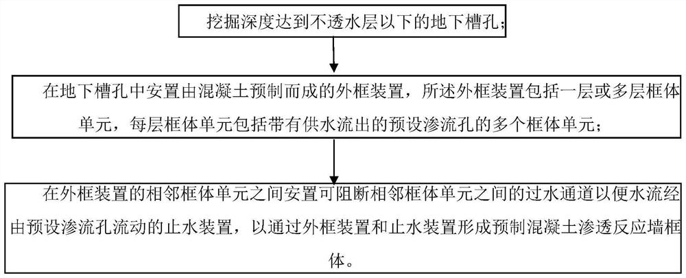
Method for realizing prefabricated concrete permeable reactive wall frame body and outer frame device
A technology of infiltration reaction wall and precast concrete, applied in chemical instruments and methods, restoration of polluted soil, treatment of polluted groundwater/leachate, etc. Prefab quality, prefab requires location-accurate effects
- Summary
- Abstract
- Description
- Claims
- Application Information
AI Technical Summary
Problems solved by technology
Method used
Image

Examples
Embodiment 1
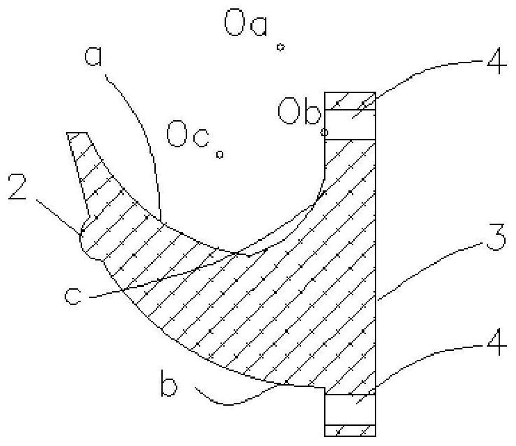
[0095] Such as Figure 10 As shown, it is a top view of this embodiment after the water stop device 100 is installed between adjacent frame units. It can be seen from the figure that the water stop device 100 of this embodiment includes a water stop unit 10, and the water stop unit 10 is placed on the Between two adjacent frame units ( Figure 10 Only two frame units are shown in the figure, and in actual application, multiple frame units may be included, and the water-tight unit 10 of this embodiment is arranged between every two adjacent frame units, wherein the frame unit Prefabricated concrete structures.
[0096] Among them, the water-stop unit 10 of this embodiment is made of elastic materials, such as EPDM rubber, so that the water-stop unit 10 has good elasticity, and can adapt to the adjacent frame unit of the groundwater reaction wall within a certain range. The gap between them plays a good role in blocking the flow of polluted water. In addition, EPDM rubber has ...
Embodiment 2
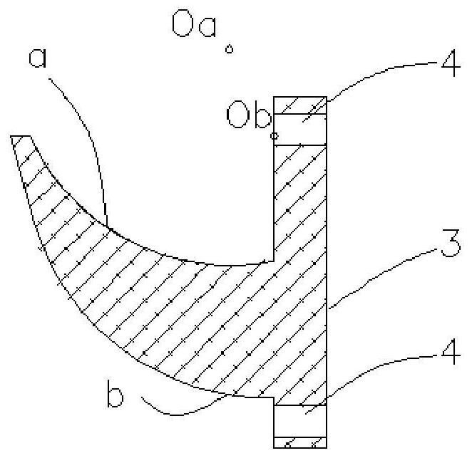
[0104] The water-stop unit adopted by the water-stop device 100 of this embodiment is as follows: image 3 The structure shown is basically the same as that of Embodiment 1. When it is placed between two adjacent frame units, the arrangement is the same as that of Embodiment 1. The difference from the water-stop unit of Embodiment 1 That is, the water-stop unit of this embodiment also has a third arc-shaped surface c and a tail ridge 2, and the first and third arc-shaped surfaces of the convex body serve as the water-facing surfaces.
[0105] In the following, only the structural differences between the water stop unit of the present embodiment and the first embodiment will be described in detail.
[0106] Since the first arc-shaped surface a of the convex body of the water-stop unit is used as the water-facing surface, the polluted water flowing in will form a greater impact on the water-stop unit. In order to prevent the first arc-shaped surface a from contacting the water-s...
Embodiment 3
[0110] The water stop unit for the water stop device 100 of this embodiment adopts the following Figure 4 The structure shown is basically the same as that of Embodiment 2, and when it is placed between two adjacent frame units, it is the same as that of Embodiment 2, that is, the first arc-shaped surface of the convex body, The third arc-shaped surface is used as the water-facing surface, and the difference from the water-stop unit of Embodiment 2 is that the water-stop unit of this embodiment also has a water-stop deformation hole 5 .
[0111] In the following, only the structural differences between the water stop unit of the present embodiment and the second embodiment will be described in detail.
[0112] Such as Figure 4 As shown, in this embodiment, a water-stop deformation hole 5 is provided near the water-stop fixing part 3 on the first arc-shaped surface a of the convex part of the water-stop unit. Preferably, the water-stop deformation hole 5 is set on the first ...
PUM
 Abstract
Description
Claims
Application Information
 - R&D
- Intellectual Property
- Life Sciences
- Materials
- Tech Scout
- Unparalleled Data Quality
- Higher Quality Content
- 60% Fewer Hallucinations
Browse by: Latest US Patents, China's latest patents, Technical Efficacy Thesaurus, Application Domain, Technology Topic, Popular Technical Reports.
© 2025 PatSnap. All rights reserved.Legal|Privacy policy|Modern Slavery Act Transparency Statement|Sitemap|About US| Contact US: help@patsnap.com