
Angle-adjustable chamfering tool

A technology of chamfering tools and angle adjustment, which is applied to the lathe tools, tool holders, manufacturing tools, etc., which can solve the problems of enterprises increasing the cost of tool purchases, chamfering processing cannot be accurately guaranteed, and tool costs remain high. Achieve the effects of ingenious and reasonable structural design, good versatility, and guaranteed processing quality

Active Publication Date: 2020-11-13
DONGFANG ELECTRIC WUHAN NUCLEAR EQUIP
View PDF11 Cites 4 Cited by
  • Summary
  • Abstract
  • Description
  • Claims
  • Application Information

AI Technical Summary

Problems solved by technology

[0003] However, there are the following technical problems in the chamfering tools for processing different angles of chamfering: on the one hand, the versatility is poor, and a variety of chamfering tools are required to process a part with a simple structure and multiple chamfering angles, and the chamfering tool with a special angle It is basically a one-time tool, and it will not be used after one use. For the enterprise, it will increase the tool purchase cost and the tool management cost, and the tool cost remains high; on the other hand, the chamfer with precision requirements It cannot be guaranteed accurately; for the above-mentioned technical problems, it is urgent for those skilled in the art to study and design a chamfering tool with adjustable angle, so as to accurately adjust the angle of the chamfering tool, expand its scope of application, and ensure the processing quality of the product; at the same time In order to greatly reduce the cost of enterprises, reduce the management of cutting tools and the difficulty of placing cutting tools on site, so as to improve the machining environment

Method used


Image

  • Angle-adjustable chamfering tool
  • Angle-adjustable chamfering tool
  • Angle-adjustable chamfering tool

Examples


Embodiment 1

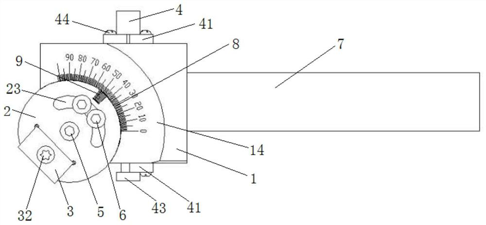
[0036] The embodiment is basically as Figure 1 to Figure 3 As shown: this embodiment provides an adjustable angle chamfering tool, including a cutter body 1, a knife seat 2 and a blade 3, and also includes an adjusting screw 4, a rotating screw 5 and a locking mechanism; the structure of the cutter body 1 is specifically as follows Figure 4 As shown, the cutter body 1 is provided with an arc-shaped mounting groove 11 for installing the cutter holder 2, so that the cutter holder 2 is rotationally connected with the cutter body 1 through the positioning round boss 21 at the bottom and the rotating screw 5, and through The locking mechanism fixes the knife seat 2 on the knife body 1. The locking mechanism includes at least two compression screws 6, and a threaded hole matched with the compression screws 6 is provided on the bottom surface of the arc-shaped installation groove 11; the knife seat The structure of 2 is as follows Figure 5 and Figure 6 As shown, the knife seat ...

Embodiment 2

[0046] Embodiment 2 is basically the same as Embodiment 1, the difference is: please combine Figure 1 to Figure 7 As shown, this implementation fully considers the precision thread cooperation between the adjusting screw 4 and the outer circular surface of the knife seat 2 to realize the precise transmission connection. Two through holes 13 are used to install the adjusting screw rod 4; and the positioning plate 41 for fixing the adjusting screw rod 4 is provided on the both sides of the cutter body 1 near the second through hole 13, and the above-mentioned structure is used to adjust the chamfering angle of the tool The adjusting screw 4 and the cutter body 1 are reliably installed together, and the matching connection between the adjusting screw 4 and the cutter seat 2 is located inside the cutter body 1 without being disturbed by the external environment.

[0047] Such as Figure 7 As shown, the middle part of the adjusting screw 4 is formed with a thread that matches the...


PUM


Abstract

The invention discloses an angle-adjustable chamfering tool, and relates to the technical field of turning and milling tools. The chamfering tool comprises a tool body, a tool apron, a blade, an adjusting screw rod, a rotating screw and a locking mechanism; an arc-shaped installation groove used for installing the tool apron is formed in the tool body, and the tool apron is rotationally connectedwith the tool body through a positioning circular boss and the rotating screw and fixed to the tool body through the locking mechanism; threads matched with the adjusting screw rod are arranged on theouter circular surface of the tool apron, so that the adjusting screw rod is in threaded fit with the tool apron to realize transmission connection; and the blade is detachably connected to the toolapron, main scale marks ranging from 0 degree to 90 degrees are arranged on the arc-shaped edge, making contact with the tool apron, of the tool body, and vernier scale marks corresponding to the mainscale marks are arranged on the tool apron. By means of the technical scheme, stepless accurate angle adjustment of the chamfering tool within the angle range of 0 degree to 90 degrees can be achieved, the application range of the chamfering tool is effectively widened, and the product machining quality is guaranteed; and meanwhile, the structure is simple, manufacturing is convenient, enterprisecost is reduced, and practicability is good.

Description

technical field [0001] The invention relates to the technical field of turning and milling tools, in particular to an angle-adjustable chamfering tool. Background technique [0002] In the field of mechanical processing technology, due to the processing of more and more complex structural parts, those skilled in the art are constantly exploring the use of versatile tools to adapt to the current complex and diverse part structures; chamfering in the prior art Most of the knives have a fixed angle, mainly according to different chamfering angles, design and manufacture different angles of chamfering knives, often a kind of angle needs to design and manufacture a kind of chamfering knives, so for various types of chamfering angle knives There will be a lot. [0003] However, there are the following technical problems in the chamfering tools for processing different angles of chamfering: on the one hand, the versatility is poor, and a variety of chamfering tools are required to...

Claims


Application Information

Patent Timeline
Patent Type & Authority Applications(China)
IPC IPC(8): B23B27/16B23B29/04
CPCB23B27/1696B23B29/04
Inventor 杨德存向志杨邓亚弟王强文小山税妍贠庆芳王春江王庆国薛强孙惠芳刘莉
Owner DONGFANG ELECTRIC WUHAN NUCLEAR EQUIP
Learn More