Sheet type buffer device for new energy automobile battery

A technology of new energy vehicles and buffer devices, applied in battery/fuel cell control devices, electric vehicles, secondary batteries, etc., can solve the problems of buffer structure occupying space, no longer suitable for battery pack buffer, single buffer function of buffer structure, etc. , to achieve the effect of improving the cooling effect

Active Publication Date: 2020-11-10
江苏众联祥博新能源科技有限公司
View PDF8 Cites 0 Cited by
  • Summary
  • Abstract
  • Description
  • Claims
  • Application Information

AI Technical Summary

Problems solved by technology

[0002] The power of new energy vehicles comes from the battery pack. At present, a big problem facing new energy vehicles is the battery life of the vehicle. Theoretically speaking, the larger the battery capacity, the greater the battery life of the vehicle, but in the process of vehicle manufacturing, it cannot be single To consider the issue of battery capacity, as well as factors such as cost, load, and space, the current solution is to increase the capacity of the battery in a limited space, so the space utilization rate of the battery in the vehicle should be as high as possible
[0003] Due to the complex driving conditions of the car, the buffering of the battery pack inside must be considered. The addition of the buffer structure will inevitably occupy a certain amount of space. The traditional spring-type buffer structure is no longer suitable for the buffering of the battery pack. , a better buffer structure is needed;
[0004] In addition, the heat dissipation of the battery pack must also be considered. The existing buffer structures often only play a buffer role. In the initial design, the buffer device and heat dissipation are rarely considered together. Therefore, the common buffer structure and heat dissipation device of the battery pack Basically, it is to separate two parts that are not related

Method used


Image

  • Sheet type buffer device for new energy automobile battery
  • Sheet type buffer device for new energy automobile battery
  • Sheet type buffer device for new energy automobile battery

Examples


Embodiment 1

[0037] Such as figure 1 As shown, the present invention provides a sheet-type buffer device for a new energy vehicle battery, which includes two parallel substrates 02, and several buffer bodies 01 are arranged between the two substrates 02, that is, the buffer body 01 is covered by two substrates. 02 clamping;

[0038] Wherein, the buffer body 01 includes a first elastic body 1 and a second elastic body 2 that are joined together. The first elastic body 1 and the second elastic body 2 are both arc-shaped plates. Specifically, the first elastic body 1 and the second elastic body The arc corresponding to the two elastic bodies 2 is a part of a parabola, a hyperbola or an ellipse, because the ellipse is a closed figure, so when it is an elliptical structure, it needs to be a part of the ellipse; in the present embodiment, the elastic body adopts a parabola structure, while a plurality of buffer bodies 01 located between two substrates 02 are distributed in a linear array, and t...

Embodiment 2

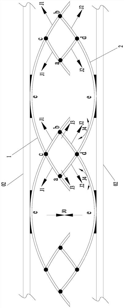
[0049] In this embodiment, on the basis of Embodiment 1, the arrangement form of the buffer body 01 is changed, that is, as image 3 As shown, two adjacent buffer bodies 01 are rotationally symmetrical, and there is a gap between two adjacent first elastic bodies 1 or between two adjacent second elastic bodies 2, the gap is set to avoid deformation When , two adjacent buffer bodies 01 come into contact; it is equivalent to figure 1 On the basis of , rotate the two buffer bodies 01 separated by 180 degrees;

[0050] This distribution method can still form overlapping spaces and enclosed spaces. Compared with Example 1, due to this arrangement, the upper layer is not all the first elastic body 1, and the lower layer is not all the second elastic body 2. In the upper and lower layers, the first elastic body 1 and the second elastic body 2 are alternately distributed, and because the opening of the first elastic body 1 covers the opening of the second elastic body 2, this distrib...

Embodiment 3

[0053] On the basis of Example 1, the angles formed between the opening end and the tip of the first elastic body 1 and the second elastic body 2 are all acute angles, that is, as Figure 5 As shown in P;

[0054] Such as Figure 5 As shown, the overlapping space at this time is still surrounded by two floating ends a and b and two fixed ends c and d. For the two adjacent buffer bodies 01 and two substrates 02 The enclosed space is still enclosed by two e and d or two e and c, and shares the fixed ends c and d with the overlapping space.

[0055] Such as Figure 6 As shown, when two substrates 02 generate relative motion, that is Figure 6 When moving in the direction of J0, the buffer body 01 will deform at this time. Taking one of the overlapping spaces and the enclosed space as an example, because the included angle P has changed, the corresponding deformation has also changed, as follows:

[0056] For the overlapping space, there are still two fixed ends c, d and two f...


PUM


Abstract

The invention discloses a sheet type buffer device for a new energy automobile battery, and the device comprises two base plates arranged in parallel, wherein a plurality of buffer bodies are arrangedbetween the two base plates; the buffer body comprises a first elastic body and a second elastic body which are folded together, wherein the first elastic body and the second elastic body are arc-shaped plates; at least one part of every two adjacent buffer bodies is overlapped to form an overlapped space, and two enclosed spaces are formed between every two adjacent buffer bodies and the two base plates. A sheet type structure is adopted, and a buffer effect different from that of a conventional spring structure is formed, so the overall buffer effect is better, the thickness of the buffer device can be reduced to a certain extent, the occupied space of the buffer device is reduced, and the utilization rate of battery pack space is increased; in addition, the buffer structure can form aheat dissipation structure while realizing buffer, and an overlapping space, an enclosing space and the like formed in the buffer structure can play a role of an air duct, so the heat dissipation effect of the battery is improved.

Description

technical field [0001] The invention relates to the technical field of battery buffer devices, in particular to a sheet-type buffer device for new energy vehicle batteries. Background technique [0002] The power of new energy vehicles comes from the battery pack. At present, a big problem facing new energy vehicles is the battery life of the vehicle. Theoretically speaking, the larger the battery capacity, the greater the battery life of the vehicle, but it cannot be singled out in the process of vehicle manufacturing. To consider the issue of battery capacity, as well as factors such as cost, load, and space, the current solution is to increase the capacity of the battery in a limited space, so the space utilization rate of the battery in the vehicle should be as high as possible. [0003] Due to the complex driving conditions of the car, the buffering of the battery pack inside must be considered. The addition of the buffer structure will inevitably occupy a certain amoun...

Claims


Application Information

Patent Timeline
Patent Type & Authority Applications(China)
IPC IPC(8): H01M2/10H01M10/613H01M10/625H01M10/6556H01M10/6561B60L50/64B60L58/26
CPCB60L50/64B60L58/26H01M10/613H01M10/625H01M10/6556H01M10/6561Y02E60/10Y02T10/70
Inventor 刘成龙涂坚胡心彬张东桥龚雪丹唐海龙
Owner 江苏众联祥博新能源科技有限公司
Why Eureka
Try Eureka