
Device for reducing ignition loss rate of incineration residues of hazardous waste incineration rotary kiln

A technology of rotary kiln and thermal loss rate, which is applied to incinerators, combustion methods, combustion types, etc., can solve the problems of high thermal loss rate of incineration residues, and achieve the effects of mature equipment structure, prolonged residence time and low noise

Pending Publication Date: 2020-11-10
杭州顶峰环保工程有限公司
View PDF0 Cites 1 Cited by
  • Summary
  • Abstract
  • Description
  • Claims
  • Application Information

AI Technical Summary

Problems solved by technology

[0004] The purpose of the embodiment of the present invention is to provide a device for reducing the thermal ignition loss rate of the incineration residue of the hazardous waste incineration rotary kiln, so as to solve the problem of high thermal ignition loss rate of the incineration residue in the prior art

Method used


Image

  • Device for reducing ignition loss rate of incineration residues of hazardous waste incineration rotary kiln
  • Device for reducing ignition loss rate of incineration residues of hazardous waste incineration rotary kiln
  • Device for reducing ignition loss rate of incineration residues of hazardous waste incineration rotary kiln

Examples


Embodiment Construction

[0022] It should be noted that, in the case of no conflict, the embodiments in the present application and the features in the embodiments can be combined with each other. The present invention will be described in detail below with reference to the accompanying drawings and examples.

[0023] It should be noted that the terminology used here is only for describing specific implementations, and is not intended to limit the exemplary implementations according to the present application. As used herein, unless the context clearly dictates otherwise, the singular is intended to include the plural, and it should also be understood that when the terms "comprising" and / or "comprising" are used in this specification, they mean There are features, steps, operations, means, components and / or combinations thereof.

[0024] For the convenience of description, spatially relative terms may be used here, such as "on ...", "over ...", "on the surface of ...", "above", etc., to describe the ...


PUM


Abstract

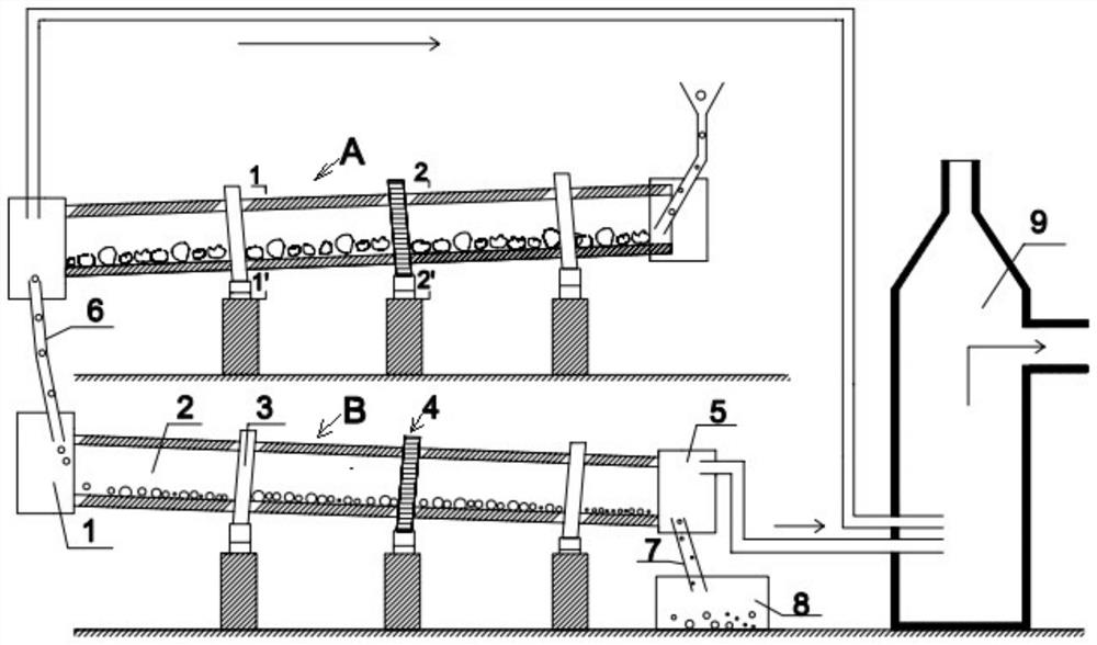
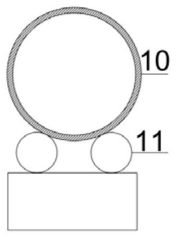
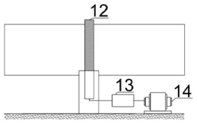
The invention discloses a device for reducing the ignition loss rate of incineration residues of a hazardous waste incineration rotary kiln. The device comprises the hazardous waste incineration rotary kiln, a special carbon residue incineration rotary kiln and a secondary combustion chamber, and the hazardous waste incineration rotary kiln and the special carbon residue incineration rotary kiln have the same structure and each comprise a feeding cover, an inner chamber, a supporting device, a transmission device and a discharging cover, wherein the inner chamber is supported on the supportingdevice, the transmission device drives the inner chamber to rotate, the feeding cover is arranged at the feeding port end of the inner chamber in a sleeving manner, and the discharging cover is arranged at the discharging port end of the inner chamber in a sleeving manner. The discharging cover of the hazardous waste incineration rotary kiln is communicated with the feeding cover of the special carbon residue incineration rotary kiln through a feeding chute; and the discharging covers of the hazardous waste incineration rotary kiln and the special carbon residue incineration rotary kiln are provided with flue gas outlets, and the flue gas outlets of the discharging covers of the hazardous waste incineration rotary kiln and the special carbon residue incineration rotary kiln are communicated with a flue gas inlet of the secondary combustion chamber through flue gas channels. The device is high in waste disposal adaptability, the incineration removal rate is larger than 99.99%, and theslag ignition loss rate is smaller than 5%.

Description

technical field [0001] The invention relates to the technical field of hazardous waste treatment, in particular to a device for reducing the loss-on-ignition rate of incineration residue in a rotary kiln for incinerating hazardous waste. Background technique [0002] With the development of social economy and urbanization, the amount of chemical and pharmaceutical hazardous waste is increasing. Hazardous waste is basically incinerated and safely landfilled. The rotary kiln is a common device for incineration. Its working principle is that hazardous waste is fed from the cold end of the kiln. Since the kiln has a 2.5%-4.5% inclination degree, and constantly rotate, so that the hazardous waste continuously moves to the hot end. The fuel is injected from the heating end, and it burns under the air-assisted combustion to release heat and generate high-temperature flue gas. Driven by the fan, the hot air flows from the heating end to the secondary end, and the residence time of ...

Claims


Application Information

Patent Timeline
IPC IPC(8): F23G5/16F23G5/20F23G5/44F23G5/46F23G5/50
CPCF23G5/16F23G5/20F23G5/444F23G5/46F23G5/50
Inventor 戴斌于学洋王瑞霞姜南姜岩王俊淇常舒婷
Owner 杭州顶峰环保工程有限公司
Learn More