
Finish machining auxiliary device suitable for concave-convex lens and uniform in cutting component force

An auxiliary device and convex lens technology, which is applied in the field of finishing parts, can solve the problems of lens deformation, deformation is difficult to control, and high defective rate, so as to improve the precision of finishing and reduce deformation.

Inactive Publication Date: 2020-11-10
缙云唐纳机械科技有限公司
View PDF0 Cites 2 Cited by
  • Summary
  • Abstract
  • Description
  • Claims
  • Application Information

AI Technical Summary

Problems solved by technology

[0002] Thin-walled parts are widely used, but their rigidity and strength are relatively weak, and the deformation is difficult to control during the processing. At present, when finishing the curved lens, with the axial movement of the grinding rod, the grinding rod will affect the curved lens. The resulting cutting force in the vertical direction is changing. Under the constantly changing external force, the arc-shaped and thinner lens is prone to deformation, and the defective rate is higher. The existing manual grinding lens is more cumbersome to operate and lowers the processing efficiency. not high

Method used


Image

  • Finish machining auxiliary device suitable for concave-convex lens and uniform in cutting component force
  • Finish machining auxiliary device suitable for concave-convex lens and uniform in cutting component force
  • Finish machining auxiliary device suitable for concave-convex lens and uniform in cutting component force

Examples


Embodiment Construction

[0016] All features disclosed in this specification, or steps in all methods or processes disclosed, can be combined in any way, except for mutually exclusive features and or steps.

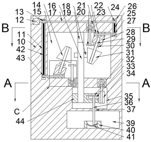
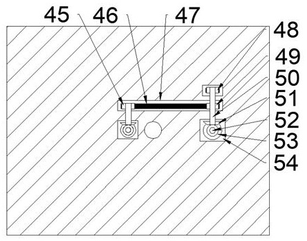
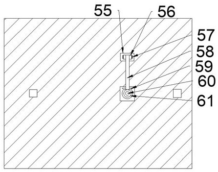
[0017] Combine below Figure 1-4 The present invention is described in detail, and for convenience of description, the orientations mentioned below are now stipulated as follows: figure 1 The up, down, left, right, front and back directions of the projection relationship itself are the same.

[0018] Such as Figure 1-4 As shown, a finishing auxiliary device suitable for concave-convex lenses and uniform cutting force of the device of the present invention includes a main box body 10, a speed change chamber 15 is arranged in the main case body 10, and a speed change chamber 15 is arranged on the right side. There is a right belt chamber 26 extending upwards, and a right screw rod 23 extending rightward into the right belt chamber 26 and leftward into the transmission chamber 15 is connected to ...


PUM


Abstract

The invention discloses a finish machining auxiliary device suitable for a concave-convex lens and uniform in cutting component force. The finish machining auxiliary device comprises a main box body,wherein a speed change cavity is arranged in the main box body; a right belt cavity extending upwards is arranged in the right side of the speed change cavity; a right screw extending rightwards intothe right belt cavity and extending leftwards into the speed change cavity is connected into the left end wall of the right belt cavity in a running fit mode; a right transmission bevel tooth cavity located in left side of right belt cavity is arranged in upper side of speed change cavity; and when the concave surface of the lens needs to be machined, the left speed change wheel just abuts againstthe speed change gear, so that the uniformity of the vertical component force during machining of the concave surface of the lens is realized, and the finish machining precision is improved. when theconvex surface of the lens needs to be machined, the change gear moves downwards, so that the rotating speed of the grinding rod is increased, the cutting force in the vertical direction is reduced,the vertical cutting component force generated on the arc-shaped lens in the machining process is uniform, and therefore deformation caused by uneven stress is reduced;.

Description

technical field [0001] The invention relates to the related technical field of component finishing, in particular to a finishing auxiliary device suitable for concave-convex lenses and having uniform cutting force components. Background technique [0002] Thin-walled parts are widely used, but their rigidity and strength are relatively weak, and the deformation is difficult to control during the processing. At present, when finishing the curved lens, with the axial movement of the grinding rod, the grinding rod will affect the curved lens. The resulting cutting force in the vertical direction is changing. Under the constantly changing external force, the arc-shaped and thinner lens is prone to deformation, and the defective rate is higher. The existing manual grinding lens is more cumbersome to operate and lowers the processing efficiency. Not high either. Contents of the invention [0003] In view of the deficiencies of the above-mentioned technologies, the present inven...

Claims


Application Information

Patent Timeline
IPC IPC(8): B23Q15/013B23Q5/02
CPCB23Q5/02B23Q15/013
Inventor 黄铮妮
Owner 缙云唐纳机械科技有限公司
Learn More