An aluminum alloy window frame based on a storage rack structure
An aluminum alloy, drying rack technology, applied in the direction of windows/doors, building components, wing fan frames, etc., can solve the problems of poor drying effect, inability to achieve hidden installation, poor weather resistance, etc., to achieve convenient operability and improve drying space. Effect
- Summary
- Abstract
- Description
- Claims
- Application Information
AI Technical Summary
Problems solved by technology
Method used
Image
Examples
Embodiment 1
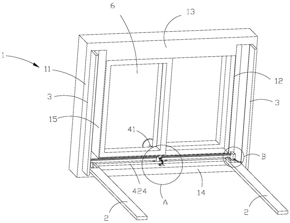
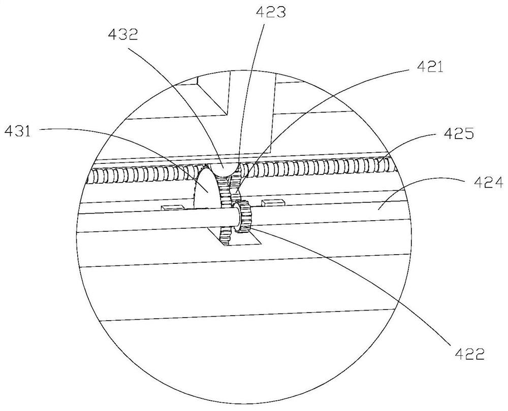
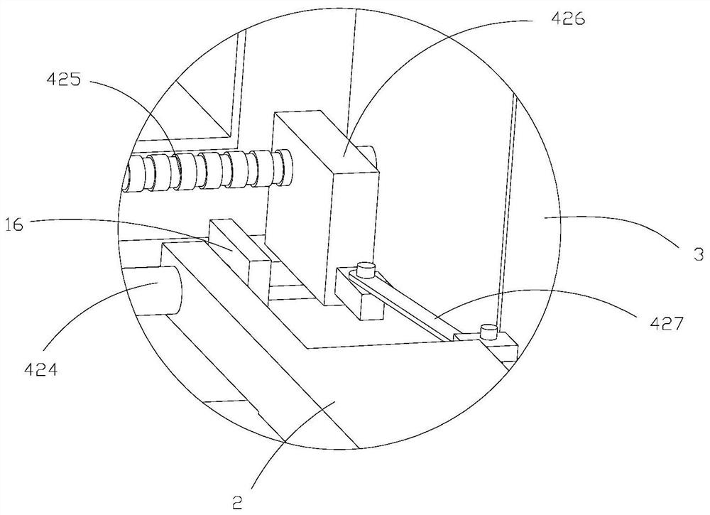
[0059] refer to Figure 1-3 , this embodiment discloses an aluminum alloy window frame based on a structure that can accommodate a drying rack, including a window frame body 1, a drying rod 2, a movable plate 3, a driving shaft 41, and a transmission assembly. The side of the window frame body 1 facing outdoors is the front side, and the side of the window frame body 1 facing indoors is the back side. The left and right ends of the window frame body 1 are respectively the left frame 11 and the right frame 12 of the window frame body 1 , and the upper and lower parts of the window frame body 1 are respectively the upper frame 13 and the lower frame 14 of the window frame body 1 .
[0060] On the front of the left frame 11 and the front of the right frame 12, there are storage grooves 15 that open outwards, and the inside of the lower frame 14 is a hollow structure. The receiving groove 15 communicates with each other to form an assembly cavity. The left frame 11 and the right...
Embodiment 2
[0076] refer to Image 6 , 7 The difference between this embodiment and the above-mentioned embodiments is that a fastening device is installed on the back of the lower frame 14 . The fastening device includes a positioning block 51 , which surrounds the outside of a section fixed in the driving shaft 41 exposed to the chamber, and preferably has a ring of raised structures 511 on the edge of the positioning block 51 or a through hole is opened on the positioning block 51 . A section of the driving shaft 41 exposed in the chamber has a positioning opening 411 with a hollow interior and an open end.
[0077] A rotating arm 521 , an elastic member 522 , and a translation rod 523 are also disposed in the positioning opening 411 . On the outer side wall of the positioning opening 411, a through groove 49 is provided, and a rotating arm 521 is rotatably connected in the through groove 49, and the curved hook end of the rotating arm 521 is stuck on the protruding structure 511 or ...
Embodiment 3
[0088] refer to Figure 10 The difference between the present embodiment and the above-mentioned embodiments is that support rods 61 are respectively fixed at the left and right ends of the lower frame 14 of the window frame body 1 or support rods are respectively fixed at the lower end of the left frame 11 and the lower end of the right frame 12. 61. The bottom of the drying rod 2 can be supported on the top of the support rod 61 after it rotates out from the storage tank 15 .
[0089] In the present invention, support rods 61 are respectively fixed at the left and right ends of the lower frame 14 of the window frame body 1 or the lower ends of the left frame 11 and the lower end of the right frame 12 are respectively fixed with support rods 61. Effect, improve the load-bearing capacity of the drying rod 2 when drying.
[0090] In some examples, refer to Figure 11 , the support rod 61 is hollow inside, both ends and the top are open, the extension rod 62 is slidingly fitt...
PUM
 Abstract
Description
Claims
Application Information
 - R&D Engineer
- R&D Manager
- IP Professional
- Industry Leading Data Capabilities
- Powerful AI technology
- Patent DNA Extraction
Browse by: Latest US Patents, China's latest patents, Technical Efficacy Thesaurus, Application Domain, Technology Topic, Popular Technical Reports.
© 2024 PatSnap. All rights reserved.Legal|Privacy policy|Modern Slavery Act Transparency Statement|Sitemap|About US| Contact US: help@patsnap.com


