Based on the window frame and intelligent aluminum alloy window that can be rotated out of the multifunctional movable rod in both directions
A technology of rotating rod and movable rod, which is applied in the direction of windows/doors, legs of general furniture, special equipment for doors/windows, etc., can solve the problems of functional integration effect to be improved, low functional integration, etc. , to achieve the effect of independence
- Summary
- Abstract
- Description
- Claims
- Application Information
AI Technical Summary
Problems solved by technology
Method used
Image
Examples
Embodiment 1
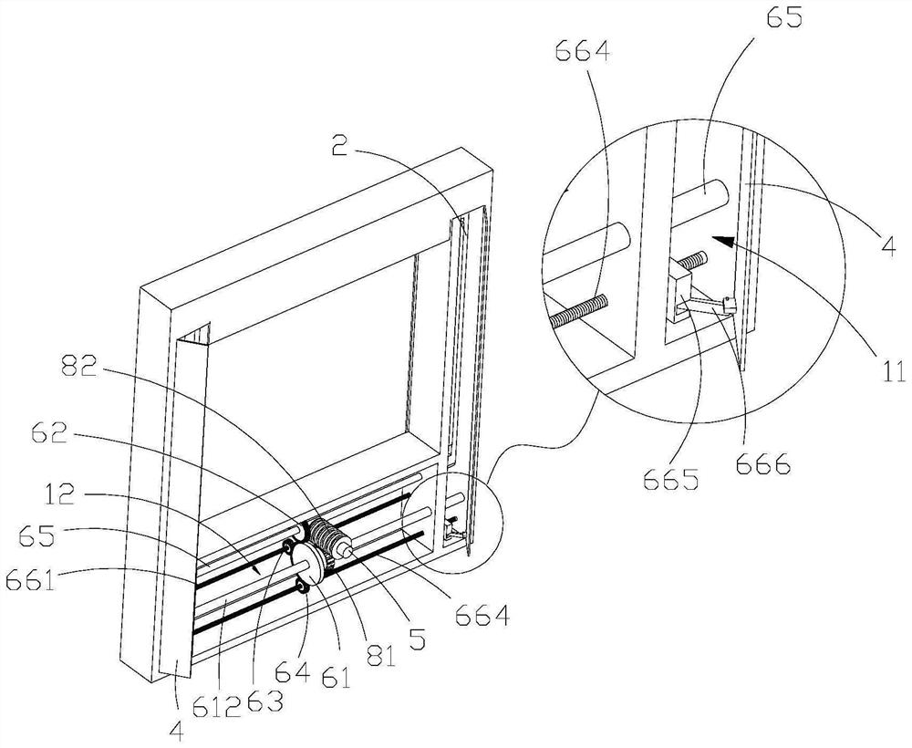
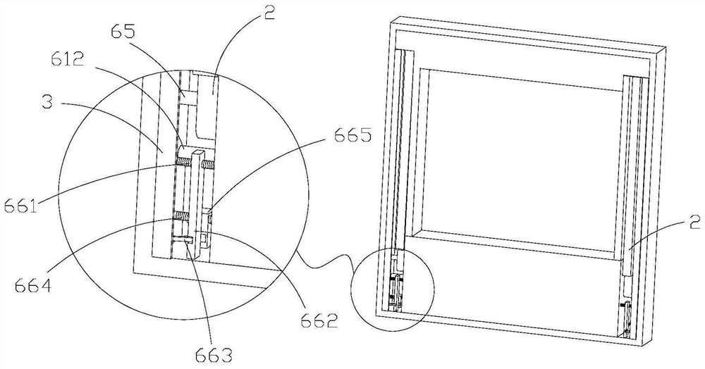
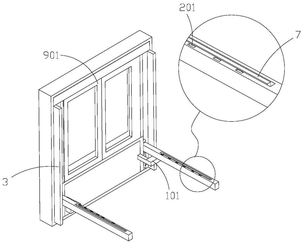
[0064] refer to Figure 1-4 , this embodiment discloses a window frame based on a multi-function movable rod that can be turned out in both directions, including a window frame body 1, a rotating rod 2, an outer door leaf plate 3, an inner door leaf plate 4, a driving shaft 5, a transmission mechanism, and a bracket 7 .
[0065] In the window frame body 1, the side facing outdoors is the front side, and the side facing indoors is the back side. The left and right ends of the window frame body 1 are the left frame and the right frame of the window frame body 1 respectively, and the upper and lower parts of the window frame body 1 are the upper frame and the lower frame of the window frame body 1 respectively.
[0066] Both left and right ends of the window frame body 1 are provided with receiving grooves 11 for internal and external communication. In the receiving groove 11, a rotating rod 2 is rotatably connected, and an outer door leaf plate 3 is respectively hinged at the ...
Embodiment 2
[0095] refer to Figure 5 , 10 The difference between this embodiment and the above-mentioned embodiments is that this embodiment provides a specific installation method for the bracket 7 .
[0096] A bar-shaped mounting groove 21 is provided on the rotating rod 2 , and when the rotating rod 2 turns inward and becomes horizontal, the opening of the bar-shaped mounting groove 21 is downward. A locking shaft 22 and a connecting shaft 23 are connected in the bar-shaped mounting groove 21 . One end of the bracket 7 is rotatably connected to the connecting shaft 23 , and when the other end 71 of the bracket can be fastened on the locking shaft 22 , the bracket 7 is limited in the bar-shaped installation groove 21 . An extension rod 711 is movably fitted on the other end 71 of the bracket. After the bracket 7 is rotated to be vertical, the elongation direction of the extension rod 711 is the vertical direction.
[0097] When the turning rod 2 rotates inwardly to a horizontal stat...
Embodiment 3
[0109] refer to Figure 13 , 14 The difference between this embodiment and the above-mentioned embodiments is that: the upper part of the window frame body 1 is provided with a top storage channel 113 for internal and external conduction, and the top storage channel 113 communicates with the storage tank 11 . A connecting rod 81 is connected between the two rotating rods 2 at the left and right ends. When the two rotating rods 2 at the left and right ends are accommodated in the corresponding receiving grooves 11 , the connecting rod 81 is accommodated in the top receiving through groove 113 .
[0110] An outer top rotating shaft 91 and an inner top rotating shaft 92 are rotatably connected in the top receiving through groove 113 . The upper end of the outer top door leaf plate 93 is connected with the outer top rotating shaft 91 , and the upper end of the inner top door leaf plate 94 is connected with the inner top rotating shaft 92 . An outer top pulley 961 and an inner t...
PUM
 Abstract
Description
Claims
Application Information
 - R&D Engineer
- R&D Manager
- IP Professional
- Industry Leading Data Capabilities
- Powerful AI technology
- Patent DNA Extraction
Browse by: Latest US Patents, China's latest patents, Technical Efficacy Thesaurus, Application Domain, Technology Topic, Popular Technical Reports.
© 2024 PatSnap. All rights reserved.Legal|Privacy policy|Modern Slavery Act Transparency Statement|Sitemap|About US| Contact US: help@patsnap.com


