Drying device

A technology of drying device and furnace body, which is applied in the directions of sludge drying, solid material drying, drying, etc., can solve the problems of low drying efficiency and poor drying effect, and achieve the effect of uniform effect and improved effect.

Active Publication Date: 2016-03-09
汪振朴
View PDF8 Cites 2 Cited by
  • Summary
  • Abstract
  • Description
  • Claims
  • Application Information

AI Technical Summary

Problems solved by technology

[0005] Therefore, the technical problem to be solved by the present invention is to overcome the defects of low drying efficiency and poor drying effect of the drying system in the prior art, thereby providing a drying system capable of improving drying efficiency and drying effect

Method used


Image

  • Drying device
  • Drying device
  • Drying device

Examples


Embodiment 1

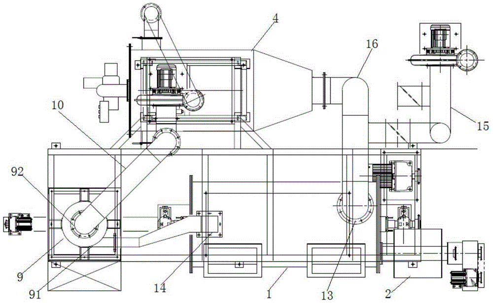
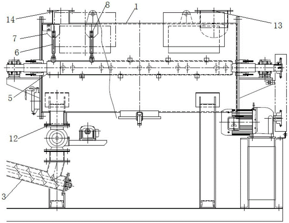
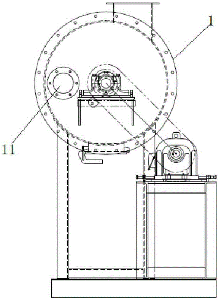
[0038] Such as figure 1 , the present embodiment provides a drying system, comprising

[0039] The furnace body 1 is arranged along the horizontal direction, and has a cavity, a material inlet 11 for feeding and taking out materials, and a material outlet 12; and a first air inlet 13 and a first air outlet 14 for heating gas to flow in and out;

[0040] The feeding device 2 is used to add materials to the furnace body 1;

[0041] The material receiving device 3 is used to collect the dried material in the furnace body 1;

[0042] Stirring device for stirring and pulverizing materials; wherein,

[0043] Stirring device includes

[0044] The rotating shaft 5 is installed in the cavity of the body of furnace 1, the rotating shaft 5 has a ventilation chamber, and several gas injection ports are arranged on the ventilation cavity, and the direction of the gas injection of the gas injection ports is the same as that of the stirring shaft 6. Stirring directions and the stirring dir...


PUM


Abstract

The invention discloses a drying device. The drying device comprises a furnace body, a charging device for charging a material into the furnace body, a collecting device for collecting a dried material in the furnace body, an air supply device for inducing external hot gas into the furnace body by a first gas inlet, and a stirring device for stirring and pulverizing the material, wherein the stirring device comprises a rotary shaft which penetrates through a cavity of the furnace body, the rotary shaft is provided with a venting cavity provided with a plurality of gas nozzles, the gas spraying direction of the gas nozzles is misaligned and not parallel with the stirring direction of the stirring device and the stirring direction of blades, during material drying, the hot gas is induced into the cavity of the furnace body by the first gas inlet, and the rotary shaft rotates to drive a stirring assembly on the rotary shaft to continuously stir the material along the axial direction and radial direction of the rotary shaft, so that the material is turned over in the furnace body along the axial direction and radial direction of the rotary shaft, the stirring time of the material is prolonged, and a convection heat exchange area between the material and the hot gas is increased. In addition, the stirring assembly can pulverize the material to form a material of smaller particles, thus further increasing the convection heat exchange area between the material and the hot gas and improving the drying efficiency and drying effect of the material.

Description

technical field [0001] The invention relates to the technical field of heating and drying, in particular to a drying system. Background technique [0002] Sludge is the product of the sewage treatment process, which contains a large amount of organic matter, heavy metals and molds, etc. If no follow-up treatment is added, it will cause serious pollution to the environment. Therefore, it is often necessary to concentrate and dehydrate the sludge, but after this treatment The moisture content of the final sludge is usually above 70%, and the sludge needs to be further dried. [0003] In the prior art, the drying system used for sludge drying is mostly structured as the drying system disclosed in the Chinese patent document CN201058838Y, including a furnace body, a feeder connected to the feed port of the furnace body, and an air outlet of the furnace body. Connected spray tower. Among them, the furnace body includes a transmission shaft arranged in the furnace body, a number...

Claims


Application Information

Patent Timeline
Patent Type & Authority Applications(China)
IPC IPC(8): F26B25/04C02F11/12
CPCC02F11/12F26B25/04F26B2200/18
Inventor 汪振朴
Owner 汪振朴
Why Eureka
Try Eureka