Manufacturing method of kidney-shaped holes in sliding support bottom plate of power station deaerator

A technology for sliding bearings and manufacturing methods, which is applied in the direction of manufacturing tools, bearings, metal processing machinery parts, etc., can solve the problems of high roughness requirements for waist-shaped holes, lack of matching drills for two-plate hole groups, and low production efficiency. The effect of improving assembly quality, optimizing manufacturing methods, and improving economic benefits

Active Publication Date: 2020-11-06
HARBIN BOILER
View PDF10 Cites 2 Cited by
  • Summary
  • Abstract
  • Description
  • Claims
  • Application Information

AI Technical Summary

Problems solved by technology

The waist-shaped holes in the bottom plate of the sliding support have been processed by CNC boring and milling machine after the sliding support is assembled and welded and the bottom plate is planed, while the matching round holes in the base plate of the sliding support are processed by a drilling machine, and there are waist-shaped holes High roughness requirements, high machining costs, low production efficiency, and lack of matching drills for the hole groups on the two plates lead to large size deviations, etc.

Method used


Image

  • Manufacturing method of kidney-shaped holes in sliding support bottom plate of power station deaerator
  • Manufacturing method of kidney-shaped holes in sliding support bottom plate of power station deaerator
  • Manufacturing method of kidney-shaped holes in sliding support bottom plate of power station deaerator

Examples


Embodiment 1

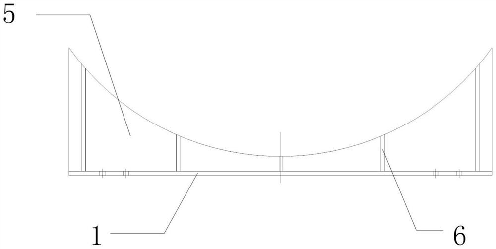
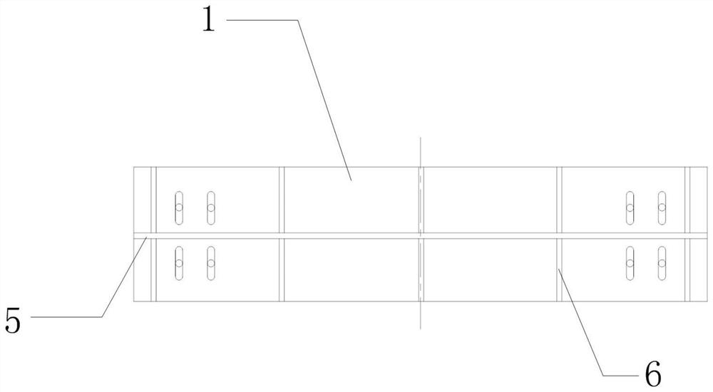
[0052] like Figure 5 and Figure 6As shown, the bottom plate of the sliding support of a deaerator in a power station, 1 piece per set, specification L×K×T=4000×500×30 (blank 34mm), specification of 8 waist-shaped holes L1×K1=260×36, spacing L2 = 160mm, spacing between waist-shaped holes at both ends L3 = 3500mm; the diameter of the corresponding sliding support foundation plate round hole d = 36mm; the roughness of the waist-shaped hole and the round hole Ra12.5μm.

[0053] In the past, the waist-shaped hole of the bottom plate of the sliding support was processed by a CNC boring and milling machine. The main process is: the bottom plate of the sliding support, the base plate CNC gas cutting→installation and welding of the sliding support assembly→correction→the bottom plate of the CNC boring and milling, the plane of the base plate→the bottom plate is drawn separately Waist-shaped hole line, foundation plate round hole line → controlled boring and milling bottom plate wais...


PUM

PropertyMeasurementUnit
surface roughnessaaaaaaaaaa

Abstract

The invention provides a manufacturing method of kidney-shaped holes in a sliding support bottom plate of a power station deaerator, and belongs to the technical field of design and manufacturing of sliding supports of large horizontal pressure bearing equipment. According to the manufacturing method, the bottom plate and a foundation plate are subjected to numerical control gas cutting blanking correspondingly, specifically, the kidney-shaped holes in the bottom plate are formed through numerical control gas cutting; the bottom plate and the foundation plate are corrected to be flat; the bottom plate, a vertical plate and rib plates are assembled and welded to form a support assembly; the bottom plate is corrected to be flat; the support assembly is put down to a flat face of the bottom plate to be fixed at the vertical position; a machined face of the bottom plate is machined, specifically, the flat faces of the opposite sides of the foundation plate and the bottom plate are independently machined; a machined surface of the foundation plate and the machined surface of the bottom plate are oppositely buckled, clamped and fixed, and after circle centers are determined or position lines of concentric circular holes are marked out on the foundation plate according to the positions of the kidney-shaped holes in the bottom plate, paired marking and disassembling are carried out; the circular holes are drilled in the foundation plate; and during construction site mounting, the bottom plate and the foundation plate are mounted according to paired marking. According to the manufacturing method of the kidney-shaped holes in the sliding support bottom plate of the power station deaerator, machined surfaces of kidney-shaped hole sets are changed into numerical control gas cut surfaces, and corresponding independent machining of the kidney-shaped hole sets and circular hole sets of the foundation plate is changed into matched machining.

Description

technical field [0001] The invention relates to a method for manufacturing a waist-shaped hole in a bottom plate of a sliding support of a deaerator in a power station, and belongs to the technical field of design and manufacture of sliding supports of large horizontal pressure-bearing equipment. Background technique [0002] For a long time, deaerators in power stations have been used as large horizontal pressure vessels, and their saddle supports include sliding supports and fixed supports. like figure 1 and figure 2 as shown in figure 1 and figure 2 As shown, the vertical plate 5 and the bottom plate of the sliding support 1 are perpendicular to each other, the bottom edge of the vertical plate 5 is welded and fixed to the bottom plate of the sliding support 1, and the vertical plate 5 is arranged at the middle position of the bottom plate of the sliding support 1 and the length is the same as that of the bottom plate of the sliding support 1 have the same length, s...

Claims


Application Information

Patent Timeline
Patent Type & Authority Applications(China)
IPC IPC(8): B23P15/00B23Q3/06
CPCB23P15/00B23Q3/06
Inventor 袁承春
Owner HARBIN BOILER
Why Eureka
Try Eureka