
High-voltage shore power supply container type heat dissipation structure

A technology of heat dissipation structure and shore power supply, which is applied in the modification of power electronics, electrical equipment structural parts, electrical components, etc., can solve the problem of reducing the service life of shore power supply, damage to cooling air duct components, waste of large area space, etc. problems, to achieve the effect of simple and fast maintenance of cooling fans, consistent air flow in and out, and stable cooling conditions

Inactive Publication Date: 2020-11-03
江苏德耐美克电气有限公司
View PDF0 Cites 2 Cited by
  • Summary
  • Abstract
  • Description
  • Claims
  • Application Information

AI Technical Summary

Problems solved by technology

[0003] At present, the construction of shore power supply is still to build a shore power room near the berth where the ship is berthed, and then lead it to the front of the wharf by high-voltage cables. This method has caused a large area of ​​waste due to the large area occupied. There have been no ships in this berth for a long time. The long-term shutdown of the high-voltage shore power supply equipment during docking greatly reduces the service life of the shore power supply. From the above points, it can be seen that the high-voltage shore power variable frequency power supply needs to be integrated into a container-type power room, which occupies a smaller area and has better flexibility. It can be moved according to the berth of the ship, only need to reserve the required cables
[0004] The heat dissipation design of the traditional high-voltage shore power supply is the front of the cabinet and the top of the cabinet. Due to the large size of the cabinet, the required air intake has strict requirements and a separate exhaust air duct is required to discharge the heat out of the container. Due to the installation of cooling fans It is difficult to maintain the fans in the air duct in the later stage. Since the air inlet of the equipment is in front of the cabinet, there must be a large air intake space in front of the cabinet. Since the air outside the container directly enters the inside of the equipment for exchange and heat dissipation, this cannot avoid the external air. Moisture and dust are directly brought into the equipment. Excessive moisture or large temperature difference will form condensation. Condensation will cause short circuit and corrosion of electronic components and cause serious damage to the equipment. Blocking and covering the components that need to be dissipated, resulting in failure of normal heat dissipation and damage to the components. From the above conditions, it can be seen that the previous methods have many disadvantages

Method used


Image

  • High-voltage shore power supply container type heat dissipation structure
  • High-voltage shore power supply container type heat dissipation structure
  • High-voltage shore power supply container type heat dissipation structure

Examples


Embodiment Construction

[0028] The following will clearly and completely describe the technical solutions in the embodiments of the present invention with reference to the drawings in the embodiments of the present invention.

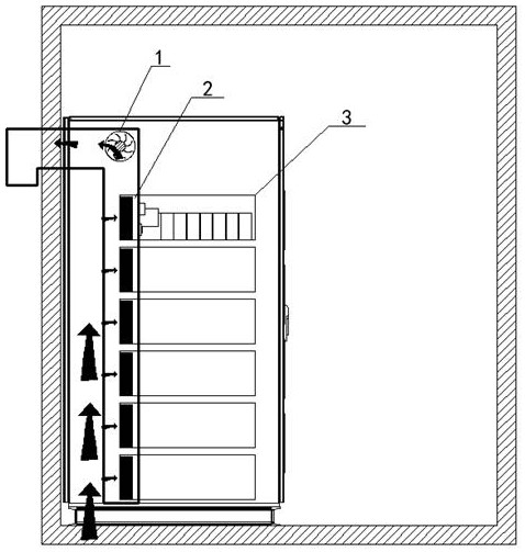
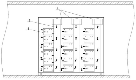
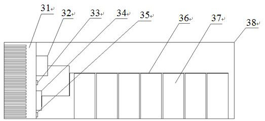
[0029] Such as figure 1 As shown, the present invention includes a container body and 3 rows of unit modules arranged in the container body, each row of unit modules is provided with 6 unit modules, and each row of unit modules 3 is provided with an independent heat dissipation fan 1 and a heat dissipation air duct 2, The heat dissipation fan 1 is fixed on the top of the heat dissipation air duct 2, and the unit module 3 is installed at the opening position of the heat dissipation air duct 2. The heat dissipation fan 1 sucks the external cold air from the air inlet at the bottom of the heat dissipation structure into the left heat dissipation air duct 2, and then passes through the units respectively. The radiator 31 of the module 3 then enters the interior of each unit module...


PUM


Abstract

The invention relates to a high-voltage shore power supply container type heat dissipation structure. Thehigh-voltage shore power supply container type heat dissipation structure is characterized by comprising a container body and three columns of unit modules (3) arranged in the container body, wherein each column of unit modules (3) is provided with six unit modules, each column of unit modules(3) is provided with an independent heat dissipation fan (1) and an independent heat dissipation air duct (2), and the heat dissipation fan (1) is arranged at the top of the heat dissipation air duct(2); the unit modules (3) are installed at the position of an opening in one side of the heat dissipation air duct (2), the heat dissipation fan (1) sucks external cold air from an air inlet in the bottom of the heat dissipation structure, the external cold air enters the left heat dissipation air duct (2) and then enters the unit modules (3) for heat dissipation, and the hot air obtained after heat dissipation is exhausted from the right heat dissipation air duct (2) and finally exhausted out of the heat dissipation structure. The high-voltage shore power supply container type heat dissipation structure is small in size and high in stability, and the service life of a high-voltage shore power supply is not influenced by corrosive gas and dust.

Description

technical field [0001] The invention relates to a novel heat dissipation structure of a high-voltage shore power variable frequency power supply, in particular to a container-type heat dissipation structure of a high-voltage shore power power supply. Background technique [0002] With the development of technology, more and more ports (docks) pay more attention to energy saving, emission reduction and pollution reduction of ports (docks). When ships are docked at ports (docks), diesel generators are still working continuously, causing air pollution and noise pollution. The electric frequency conversion power supply effectively solves this problem. When the ship is docked, the diesel generator on the ship is turned off and relies on the shore power supply for power supply. The high-voltage shore power supply is adjustable in frequency / voltage, so both domestic ships and foreign ships can use shore power supply. [0003] At present, the construction of shore power supply is st...

Claims


Application Information

Patent Timeline
IPC IPC(8): H05K7/20
CPCH05K7/20145H05K7/20172H05K7/20909
Inventor 戚永意曹森刘金晨
Owner 江苏德耐美克电气有限公司
Learn More