Generator charging and discharging circuit

A technology for charging and discharging circuits and generators, applied in battery circuit devices, circuit devices, current collectors, etc., can solve the problems of reduced service life, high cost, complicated circuit design, etc., and achieve stable performance, long service life, and input voltage. broad effect

Inactive Publication Date: 2020-11-03
胡小舟 +2
View PDF0 Cites 0 Cited by
  • Summary
  • Abstract
  • Description
  • Claims
  • Application Information

AI Technical Summary

Problems solved by technology

In this process, batteries are usually used to charge and discharge electric energy, and the service life of batteries will be significantly reduced after high-frequency charge and discharge; while in other solutions, advanced chips need to be used to ensure control of the circuit to improve charge and discharge. control, complex circuit design and high cost

Method used


Image

  • Generator charging and discharging circuit

Examples


Embodiment 1

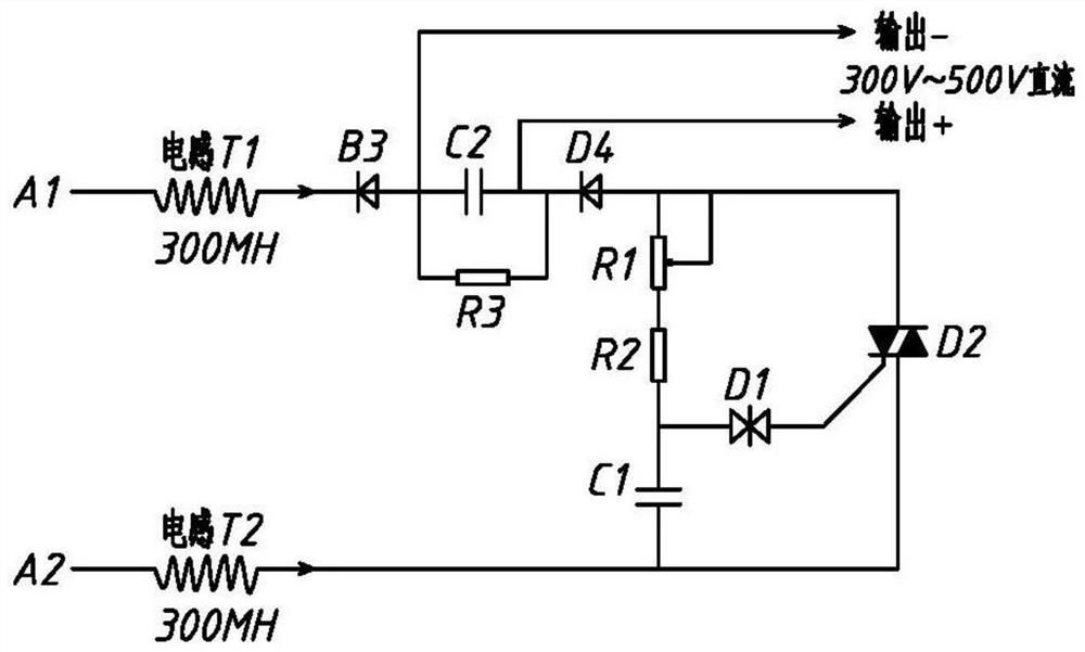
[0014] Example 1: Such as figure 1 The generator charging and discharging circuit shown includes an inductor T1, an inductor T2, a diode B3, an electrolytic capacitor C2, a resistor R1, a resistor R2, a resistor R3, a bidirectional, a trigger diode D1, a diode D4, and a triac D2.

[0015] The 220V input of A1 and A2 is filtered by inductors T1 and T2. The inductance values ​​of inductors T1 and T2 are in the range of 20mh-300mh. The output of inductor T1 is connected in series with high current rectifier diode B3. The withstand voltage of rectifier diode B3 is 1200v and current is 10A. -600A, the anode of rectifier diode B3 to the cathode of electrolytic capacitor C2. The cathode of the high current rectifier diode D4 to the anode of the electrolytic capacitor C2, the withstand voltage value of the electrolytic capacitor C2 is 350V-650V, and the capacitance range is 6800uf-60000uf. Resistor R3 is a voltage-limiting resistor connected in parallel to the electrolytic capacitor, R3...


PUM

PropertyMeasurementUnit
currentaaaaaaaaaa

Abstract

The invention discloses a generator charging and discharging circuit. Herein 220V electricity is input through an inductor T1 and an inductor T2, the inductor T1 is connected with the negative electrode of a rectifier diode B3, the positive electrode of the rectifier diode B3 is connected with the negative electrode of an electrolytic capacitor C2, the positive electrode of the electrolytic capacitor is connected with the negative electrode of a rectifier diode D4, and the electrolytic capacitor C2 is connected with a resistor R3 in parallel; the positive electrode of the rectifier diode D4 isconnected to the inductor T2 through the controllable resistor R1, the resistor R2 and the capacitor C1, the output end of the resistor R2 is connected with the control end of the bidirectional silicon controlled rectifier D2 through the trigger diode D1, the inductor T2 is connected with one output end of the bidirectional silicon controlled rectifier D2, and the other output end of the bidirectional silicon controlled rectifier D2 is connected with the positive electrode of the rectifier diode D4. The generator charging and discharging circuit provided by the invention is low in loss, stable in performance, capable of outputting 300V-500V direct current, stable and adjustable in output voltage, high in efficiency and long in service life.

Description

Technical field [0001] The invention relates to the technical field of charging and discharging, in particular to a generator charging and discharging circuit. Background technique [0002] After the existing generators generate electricity, after being stabilized and filtered, they directly provide alternating current to the load, or rectify it into direct current through a rectifier, and then output it. In this process, the battery is usually used for charging and discharging electric energy, and the service life of the battery will be significantly reduced after high-frequency charging and discharging. In other solutions, advanced chips are required to ensure the control of the circuit to improve charging and discharging. The circuit design is complicated and the cost is high. Summary of the invention [0003] Objective of the invention: The objective of the present invention is to provide a generator charging and discharging circuit in view of the shortcomings of the prior ar...

Claims


Application Information

Patent Timeline
Patent Type & Authority Applications(China)
IPC IPC(8): H02J7/06H02J7/10H02M7/217H02M3/06
CPCH02J7/06H02M3/06H02M7/217
Inventor 胡小舟吴国平邢明亮
Owner 胡小舟
Why Eureka
Try Eureka