Furnace core coil type high-medium-low frequency smelting furnace

A smelting furnace and furnace core technology, which is applied to furnaces, crucible furnaces, furnace types, etc., can solve the problems that the volume of the smelting furnace cannot be too large, the smelting loss is large, and the heating temperature is slow.

Inactive Publication Date: 2016-11-09
巴涌
View PDF0 Cites 2 Cited by
  • Summary
  • Abstract
  • Description
  • Claims
  • Application Information

AI Technical Summary

Problems solved by technology

[0002] Traditional high-, medium- and low-frequency melting furnaces all adopt hollow furnaces. The inside of the furnace shell is made of insulating refractory materials. There are no coils and magnets in the middle of the furnace. Water cables are used to supply coils outside the furnace shell of the furnace. The refractory brick in the furnace shell should not be too thick, otherwise it will affect the heating depth of the smelting furnace, and the volume of the smelting furnace itself should not be too large; The temperature rise is very slow, the heating and heating of the furnace core will be relatively low, and the reactive power loss is also large, requiring a large amount of capacitance compensation, and generating large harmonics, which seriously affects the production effect of the melting furnace, and the heating heat loss per unit of material is relatively large, and frequency The life of refractory materials for smelting furnace lining is short, and frequent furnace repairs increase the production cost of the enterprise; in the later stage of smelting, because the temperature of the material exceeds the Curie point, the temperature of the material rises slowly after paramagnetic, and the smelting loss is very large

Method used


Image

  • Furnace core coil type high-medium-low frequency smelting furnace
  • Furnace core coil type high-medium-low frequency smelting furnace

Examples


Embodiment Construction

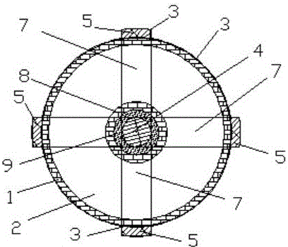
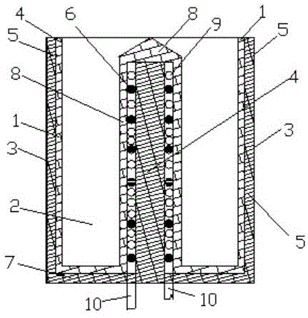
[0013] 1) Make a cross or spoke-shaped iron core (7) in the bottom of the melting furnace in the furnace shell, fix a square or round iron core (4) in the middle, and the height of the iron core should not exceed the melting furnace mouth, and design the iron core according to the needs of smelting high;

[0014] 2) Set the cooling water coil and the water supply coil coil outside the center iron core, and the cooling water of the furnace core power supply coil and the power supply interface of the water cable are drawn out at the bottom of the furnace;

[0015] 3) The furnace shell is designed with a furnace shell iron core in the furnace shell corresponding to the furnace bottom conductive core, and the furnace shell magnetic core reaches the height of the furnace mouth;

[0016] 5) Insulate and insulate the inner side of the furnace shell, the bottom of the furnace, the power supply coil of the furnace core and the outer side of the independent iron core. The insulation of...


PUM


Abstract

Disclosed is a furnace core coil type high-medium-low frequency smelting furnace. A furnace core power supply coil and a center iron core are designed in the center of a combustion chamber of the high-medium-low frequency smelting furnace. The furnace core power supply coil is wound on the center iron core. The center iron core is fixed to the center of the furnace bottom perpendicularly, or the center iron core in the combustion chamber and part of an iron core arranged at the furnace bottom and on a furnace shell form an E-shaped magnetic field loop. The furnace core power supply coil and the center iron core have cooling measures. The middle of the furnace bottom of the smelting furnace is provided with cooling medium inlet-outlet connectors of the furnace core power supply coil and the center iron core. Insulation and refractory materials are arranged outside the center iron core and the furnace core power supply coil, and the center iron core and the furnace core power supply coil are isolated from combustion chamber working materials. Magnetism isolating is conducted on the furnace bottom of the combustion chamber of the smelting furnace and the furnace shell, suitable materials are selected, a closed loop and eddy heating are prevented, and water cooling is conducted on the smelting furnace shell in necessity.

Description

Technical field: [0001] High, medium and low frequency melting furnaces are important devices for metal casting and scrap metal smelting, and their power consumption accounts for more than 20% of China's total annual electricity consumption. and the key to efficient smelting. Background technique: [0002] Traditional high-, medium- and low-frequency melting furnaces all adopt hollow furnaces. The inside of the furnace shell is made of insulating refractory materials. There are no coils and magnets in the middle of the furnace. Water cables are used to supply coils outside the furnace shell of the furnace. The refractory brick in the furnace shell should not be too thick, otherwise it will affect the heating depth of the smelting furnace, and the volume of the smelting furnace itself should not be too large; The temperature rise is very slow, the heating and heating of the furnace core will be relatively low, and the reactive power loss is also large, requiring a large amou...

Claims


Application Information

Patent Timeline
Patent Type & Authority Applications(China)
IPC IPC(8): F27B14/06F27B14/14
CPCF27B14/061F27B14/14
Inventor 不公告发明人
Owner 巴涌
Why Eureka
Try Eureka