
Automatic Switching Circuit and Method for Two-way DC Input Power Supply of Power Electronic Converter

A technology of power electronics and DC power supply, which is applied in the direction of high-efficiency power electronics conversion, parallel operation of DC power supplies, and DC network circuit devices. problem, to achieve reliable principle, shorten switching time, and realize convenient effect

Active Publication Date: 2022-03-15
HUAZHONG UNIV OF SCI & TECH
View PDF0 Cites 0 Cited by
  • Summary
  • Abstract
  • Description
  • Claims
  • Application Information

AI Technical Summary

Problems solved by technology

[0004] Aiming at the defects and improvement needs of the prior art, the present invention provides an automatic switching circuit and method for two DC input power supplies of a power electronic converter. There is a high probability of shutdown and the technical problem that the electrolytic capacitor pumps the voltage too high when the motor load decelerates or stops suddenly

Method used


Image

  • Automatic Switching Circuit and Method for Two-way DC Input Power Supply of Power Electronic Converter

Examples


Embodiment Construction

[0031] In order to make the object, technical solution and advantages of the present invention clearer, the present invention will be further described in detail below in conjunction with the accompanying drawings and embodiments. It should be understood that the specific embodiments described here are only used to explain the present invention, not to limit the present invention. In addition, the technical features involved in the various embodiments of the present invention described below can be combined with each other as long as they do not constitute a conflict with each other.

[0032] The present invention will be further explained below in conjunction with the accompanying drawings.

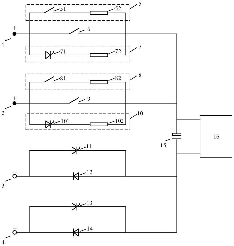
[0033] Such as figure 1 As shown, it is a schematic diagram of an automatic switching circuit for two DC input power supplies of a power electronic converter provided by the present invention, including a main / standby power supply precharging branch, a working branch, a switching branch...


PUM


Abstract

The invention discloses an automatic switching circuit and method for two-way DC input power sources of a power electronic converter. Boost voltage branch and negative working branch. Use the main / standby DC power supply pre-charging branch to realize the pre-charging of the electrolytic capacitor on the DC input side of the power electronic converter before starting; use the main / standby DC power supply working branch, negative working branch and switching branch to realize the power electronic converter start-up The final main or backup DC power supply, and the subsequent power electronic converter work according to the main / standby DC power supply situation, to realize the fast switching of the main / standby DC power supply; use the main / standby DC power supply to pump up the voltage branch and The working branch realizes the removal of the voltage pumped by the electrolytic capacitor when the motor load decelerates or stops suddenly. The principle of the invention is reliable and the realization is convenient.

Description

technical field [0001] The invention belongs to the field of power electronic converters, and more specifically relates to an automatic switching circuit and method for two DC input power sources of a power electronic converter. Background technique [0002] With the increasingly widespread application of power electronic converters, people have put forward higher requirements for their safety. The DC input side of the power electronic converter is faced with the problems of excessive direct charging current of the electrolytic capacitor, a high probability of failure shutdown when the DC power supply is supplied, and too high voltage pumped by the electrolytic capacitor when the motor load decelerates or stops suddenly. Any problem will affect the safe and stable operation of the power electronic converter. [0003] In the existing DC power supply scheme for power electronic converters, when solving the problem of excessive charging current of electrolytic capacitors and s...

Claims


Application Information

Patent Timeline
Patent Type & Authority Patents(China)
IPC IPC(8): H02J1/10H02J9/06H02J7/34H02H7/12H02H11/00H02M1/32
CPCH02J1/109H02J9/061H02J7/345H02H7/1213H02H11/002H02M1/32H02M1/322Y02B70/10
Inventor 彭力徐茂宁刘新民康勇
Owner HUAZHONG UNIV OF SCI & TECH
Learn More