
Part space size detection method

A detection method and technology of space size, applied in mechanical gap measurement, measurement device, mechanical measurement device, etc., can solve the problems of large error in detection results, affecting measurement efficiency, labor cost, etc., to achieve low cost and ensure accuracy , the effect of improving convenience

Inactive Publication Date: 2020-11-03
SICHUAN AEROSPACE LONG MARCH EQUIP MFG CO LTD
View PDF3 Cites 3 Cited by
  • Summary
  • Abstract
  • Description
  • Claims
  • Application Information

AI Technical Summary

Problems solved by technology

Then in the actual processing and testing process, the dimensions marked on individual design drawings cannot be directly detected, such as various special-shaped parts in aerospace and related industries, especially irregular sheet metal parts with non-90° included angles. After manual bending and forming, there are various angle structures and the space extension lines formed with these angle structures, and the space points formed by the intersection of space extension lines. In actual processing, it is necessary to ensure and detect the holes between these space points and the solid holes. The distance dimension or the length dimension between the space point and the entity side, but these space points and space extension lines are all virtual and cannot be used as actual measurement benchmarks during detection
[0003] In order to solve the problem of measuring the dimensions related to spatial points, traditional measuring instruments can be used, such as vernier calipers, etc., but two people must cooperate. One of them holds a steel plate or a measuring block close to the angle edge to obtain the measurement reference, and the other holds it. Calipers measure the defined measurement benchmarks. This method consumes a lot of labor costs, and the measurement accuracy is not high, and large measurement errors are prone to occur.
[0004] Another method is to use a special angle caliper or a profile sample for testing, but each specification part needs to be equipped with a corresponding sample, so this method is not suitable for the measurement of small and medium batches of multiple specifications and types of parts, and the sample test at the same time , the measurement process is not easy to control, affected by the strength of the inspector's hand, the position of the force and the width of the measuring tool, the error of the test result is relatively large, and multiple measurements are required to obtain the average value, which affects the measurement efficiency; and the detection accuracy of the sample is not high ( Usually 0.5 ~ 0.3mm), for the production and acceptance of high precision products such as aerospace Tiangong products connecting angle piece parts, due to the high precision of the relevant space dimensions of the parts (sheet metal tolerance ± 0.1mm), it is impossible to use the model Make a valid check
[0005] Another measurement method is to use three-coordinate measuring equipment for fitting detection. Due to the high cost of the testing equipment and the cumbersome testing operations, the three-coordinate measuring equipment is usually used for the first-piece inspection of mass-produced products or the inspection of single task parts. As a sheet metal part with poor consistency, if each product is inspected, the production efficiency will be greatly reduced, and it will also be a waste of expensive Sanzuobao measuring equipment
[0006] In summary, the existing technology does not have an effective way to measure the relative spatial dimensions of non-90° included angle parts, so how to quickly and accurately detect the relative dimensions of product spatial points has become a current research direction

Method used


Image

  • Part space size detection method
  • Part space size detection method
  • Part space size detection method

Examples


Embodiment Construction

[0065] In order to make the purpose, technical solutions and advantages of the present invention clearer, the present invention will be further described in detail below in conjunction with the examples and accompanying drawings. As a limitation of the present invention.

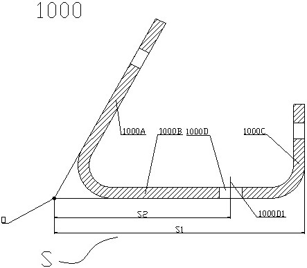
[0066] In some embodiments, a method for detecting the space size of a part is provided, the part 1000 is as figure 1 The shown is usually a sheet metal structure, which is formed by stamping or manual bending. Specifically, a rectangular sheet metal part is bent on both sides to form the second included angle side 1000B in the middle and the second included angle The first angled side 1000A and the right-angled side 1000C at both ends of the side 1000B. The second angled side 1000B and the right angled side 1000C are perpendicular to each other, and the angle between the first angled side 1000A and the second angled side 1000B is not 90°. The intersection of the first angled side 1000A and the second angl...


PUM


Abstract

The invention discloses a part space size detection method, and the method comprises the steps: enabling an angle ruler and a right-angle ruler to be matched for use when the length dimension betweena spatial point and a solid edge is measured, and respectively defining two included angle edges of a non-90-degree included angle of the part through the long ruler edge of the right-angle ruler andthe angle ruler edge of the angle ruler; constructing extension lines of two included angle edges, constructing a space intersection point of the extension lines of the two included angle edges, defining a part entity edge by using a short ruler edge of the square, and using a vernier caliper to know the length dimension between the part entity edge and a space point; when the hole distance size between the space point and the solid hole is measured, configuring a corresponding plug block for the solid hole, inserting the plug block into the solid hole in a sliding fit manner, constructing a hole axis of the solid hole, then using a straight ruler and a vernier universal ruler in a matched manner, and respectively constructing an extension line and an extension line space intersection point of two non-90-degree included angle sides; and knowing the pitch size between the part solid hole and the space point by matching with a vernier caliper.

Description

technical field [0001] The invention relates to the field of machining measurement, in particular to a method for detecting the space size of parts. Background technique [0002] The parts need to be processed according to the design drawings and inspected after processing. Then in the actual processing and testing process, the dimensions marked on individual design drawings cannot be directly detected, such as various special-shaped parts in aerospace and related industries, especially irregular sheet metal parts with non-90° included angles. After manual bending and forming, there are various angle structures and the space extension lines formed with these angle structures, and the space points formed by the intersection of space extension lines. In actual processing, it is necessary to ensure and detect the holes between these space points and the solid holes. The distance dimension or the length dimension between the space point and the entity side, but these space poin...

Claims


Application Information

Patent Timeline
Patent Type & Authority Applications(China)
IPC IPC(8): G01B5/20G01B5/02G01B5/24G01B5/14
CPCG01B5/02G01B5/14G01B5/20G01B5/24
Inventor 凃强栾朝阳张洪斌王洁李小驹胡国平杜寿春谢玲杜娟
Owner SICHUAN AEROSPACE LONG MARCH EQUIP MFG CO LTD
Learn More