
Ion thruster

A technology of ion thrusters and positive ions, applied in the direction of using plasma, thrust reversers, machines/engines, etc., can solve the problems of reducing the electrical performance of ion thrusters, reducing the payload ratio of spacecraft, etc.

Pending Publication Date: 2020-11-03
HUADONG PHOTOELECTRIC TECHN INST OF ANHUI PROVINCE
View PDF5 Cites 0 Cited by
  • Summary
  • Abstract
  • Description
  • Claims
  • Application Information

AI Technical Summary

Problems solved by technology

[0004] Because in the ion thruster, it is the positive ion source that plays the role of thrust, and the related electron source only plays an auxiliary role in neutralizing the positive ions and balancing the electrical neutrality of the spacecraft. The electron source and its related components reduce the ion thruster’s electric performance, reducing the payload ratio of the spacecraft

Method used


Image

  • Ion thruster
  • Ion thruster

Examples


Embodiment Construction

[0022] Specific embodiments of the present invention will be described in detail below in conjunction with the accompanying drawings. It should be understood that the specific embodiments described here are only used to illustrate and explain the present invention, and are not intended to limit the present invention.

[0023] In the present invention, in the absence of a contrary description, the orientation words included in the term, such as "inner, outer, front, rear", etc., only represent the orientation of the term in the normal use state, or are understood by those skilled in the art. colloquial term and should not be construed as a limitation of the term.

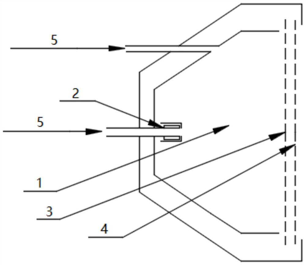
[0024] see figure 1 , the present invention provides an ion thruster, comprising an ionization chamber 1, a main cathode 2 arranged in front of the ionization chamber 1, a screen grid 3 and an accelerating grid 4 arranged sequentially behind the ionization chamber 1 from front to back; wherein, the main cathode 2 T...


PUM


Abstract

The invention discloses an ion thruster which comprises an ionization chamber, a main cathode arranged in front of the ionization chamber, a screen grid and an acceleration grid, wherein the screen grid and the acceleration grid are sequentially arranged behind the ionization chamber from front to back. A main cathode channel is formed in the main cathode, and an inlet channel is formed in the side, located on the main cathode, of the ionization chamber, so that propelling gas can be injected into the ionization chamber through the main cathode channel and the inlet channel; the main cathode is used for emitting electrons to the ionization chamber to collide with the propelling gas, so that the propelling gas is ionized into positive ions and electrons, and the gas in the ionization chamber is in a plasma state; at the moment, pulse voltage is applied to the acceleration grid, and when the voltage is positive, the electrons are accelerated from the ionization chamber and emitted out from holes of the screen grid and the acceleration grid; and when the voltage is negative, positive ions are accelerated from the ionization chamber and emitted out from the holes of the screen grid andthe acceleration grid to generate thrust opposite to the ion motion direction to push a spacecraft to do accelerated motion. The ion thruster is feasible in principle, the structure is simple, and the use efficiency of the spacecraft is effectively improved.

Description

technical field [0001] The invention relates to the field of space thrusters, in particular to an ion thruster. Background technique [0002] Ion propulsion, also known as ion engine, is a kind of space electric propulsion technology. It has the characteristics of high specific impulse, high efficiency and low thrust. It is widely used in space propulsion, such as spacecraft attitude adjustment control, position maintenance, orbital maneuvering and interstellar flight etc. Its principle is to ionize the gaseous working medium, accelerate the ejection of positive ions under the action of a strong electric field, and push the satellite to perform attitude adjustment or orbit transfer tasks through the reaction force. Compared with traditional chemical propulsion, ion propulsion requires a smaller mass of working fluid, and is the most suitable for long-distance navigation among the practical propulsion technologies. [0003] During the working process, the ion thruster obtai...

Claims


Application Information

Patent Timeline
IPC IPC(8): F03H1/00
CPCF03H1/0037F03H1/0043F03H1/0006F03H1/0025
Inventor 沈旭东赵艳珩朱荣帅
Owner HUADONG PHOTOELECTRIC TECHN INST OF ANHUI PROVINCE
Learn More