Oil-water separator

A technology of oil-water separator and oil layer, which is applied in the field of waste oil recovery devices, can solve the problems of low reliability, short life, and emulsion affecting machinability, etc., and achieve the effect of avoiding the impact

Pending Publication Date: 2020-11-03
NANJING COLLEGE OF INFORMATION TECH
View PDF4 Cites 0 Cited by
  • Summary
  • Abstract
  • Description
  • Claims
  • Application Information

AI Technical Summary

Problems solved by technology

[0003] In the prior art, a water storage tank installed at the bottom of the CNC machine tool is used to recover the cutting fluid. The emulsion stored in the water storage tank includes the waste oil generated by lubrication, and the oil and water are mixed together, which easily leads to two consequences: one is easy to emulsify The phase change of the cutting fluid affects the machinability. The second is that too much oil floats on the upper layer of the cutting fluid, which isolates the emulsion from the air and promotes anaerobic reaction, which produces foul odor and pollutes the environment.
At present, the methods mainly adopt mechanical oil skimming methods such as sponge oil skimmers. These methods have disadvantages such as low reliability, unclean skimming, short life, and large space occupation.

Method used


Image

  • Oil-water separator
  • Oil-water separator

Examples


Embodiment Construction

[0017] In order to make the object, technical solution and advantages of the present invention clearer, the present invention will be further described in detail below in conjunction with the examples. It should be understood that the specific embodiments described here are only used to explain the present invention, not to limit the present invention.

[0018] The application principle of the present invention will be described in detail below in conjunction with the accompanying drawings.

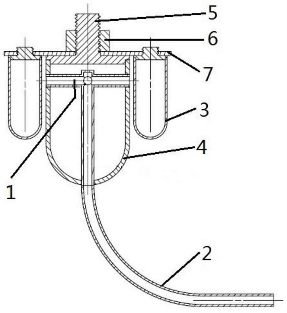
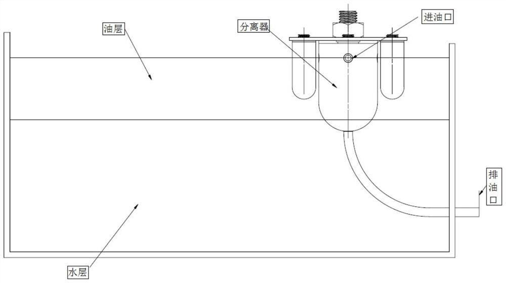
[0019] An oil-water separator designed in the present invention is suspended in the emulsion system with to-be-separated. The oil-water separator mainly includes an interconnected oil guide unit and a buoyancy adjustment mechanism. The buoyancy adjustment mechanism adjusts the guide The inlet end of the oil pipe unit is submerged into the most suitable depth position for collecting the oil layer in the oil layer. After verification, it is found that when the waste oil port is submerged i...


PUM


Abstract

The invention discloses an oil-water separator which comprises an oil guide pipe unit and a buoyancy adjusting mechanism which are connected with each other, and the buoyancy adjusting mechanism adjusts the depth position of the inlet end, immersed in an oil layer, of the oil guide pipe unit. According to the separator designed by the invention, the relative height of a float bowl can be conveniently changed by adjusting the buoyancy adjusting mechanism, and the inlet end of the oil guide pipe unit for collecting waste oil is positioned at the optimal depth position, so that the influence of the height change of emulsified liquid on the position of the inlet end is avoided.

Description

technical field [0001] The invention belongs to the field of waste oil recovery devices, and in particular relates to an oil-water separator. Background technique [0002] CNC cutting machine tools need to automatically lubricate moving parts while working, and need to automatically pour cutting fluid on the other hand. The motion structure of CNC machine tools determines that its lubrication system is open lubrication, that is, lubricating oil (mineral oil) is sprayed onto the surface of moving parts, and the moving parts slide against each other to form a lubricating oil film. This mutual movement will inevitably consume lubricating oil continuously and generate Oil is flowing out. In the metal cutting system, a large amount of cutting fluid (emulsion - the main component is water-based) is continuously poured, and these cutting fluids must be recycled. [0003] In the prior art, a water storage tank installed at the bottom of the CNC machine tool is used to recover the ...

Claims


Application Information

Patent Timeline
IPC IPC(8): B23Q11/00B23Q11/10B01D17/02
CPCB23Q11/10B23Q11/00B23Q11/1069B01D17/0214
Inventor 马云鹏丁友生温上樵任长春
Owner NANJING COLLEGE OF INFORMATION TECH
Why Eureka
Try Eureka