Reinforced concrete waste treatment device

A reinforced concrete and waste treatment technology, applied in grain treatment, magnetic separation, solid separation, etc., can solve the problem of separation of steel bars and concrete

Active Publication Date: 2020-11-03
SHANGHAI NO 4 CONSTR
View PDF8 Cites 5 Cited by
  • Summary
  • Abstract
  • Description
  • Claims
  • Application Information

AI Technical Summary

Problems solved by technology

[0004] The present invention intends to provide a reinforced concrete waste treatment device to solve the problem of separation of steel bars and concrete in reinforced concrete waste

Method used


Image

  • Reinforced concrete waste treatment device
  • Reinforced concrete waste treatment device
  • Reinforced concrete waste treatment device

Examples


Embodiment

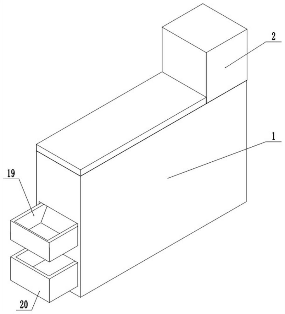
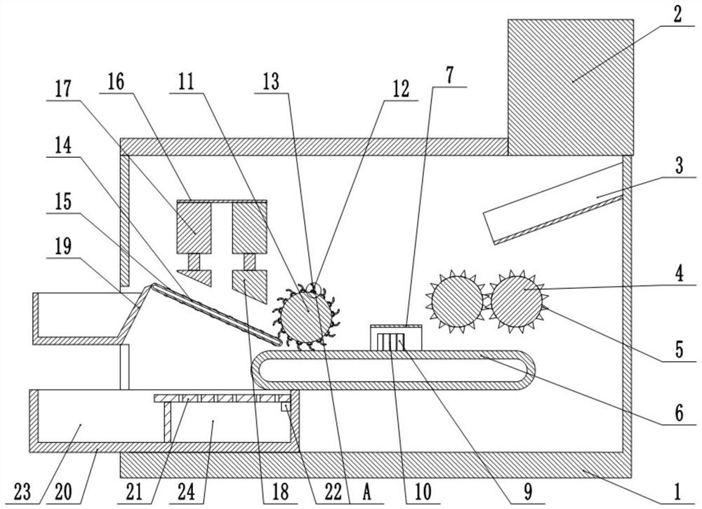
[0024] Such as figure 1 , figure 2 , image 3 and Figure 4 Shown: a reinforced concrete waste processing device, including a crushing box 1, a jaw crusher is arranged in the crushing box 1, and an inclined slideway 3 is fixed at the output end of the jaw crusher, and the lowest end of the slideway 3 is A crushing device is provided. The crushing device includes two crushing rollers 4 arranged in parallel. The crushing rollers 4 are rotatably connected to the inner wall of the crushing box 1. The two crushing rollers 4 rotate in opposite directions. Several crushing thorns 5 are distributed on the surface of the crushing roller 4, and The crushing thorns 5 between the adjacent crushing rollers 4 are alternately distributed; the first conveyor belt 6 is fixed below the crushing rollers 4, and a concrete recovery box 20 is arranged below the end of the first conveyor belt 6, and the concrete recovery box 20 includes coarse bone particles. Zone 23 and fine material zone 24, t...

specific Embodiment approach

[0025] Put the reinforced concrete into the jaw crusher 2 for the first crushing, crush the reinforced concrete into small pieces and drop it onto the slideway 3, drop it along the slideway 3 to the crushing roller 4, and then pass through the crushing roller 4 Carry out the second crushing, crush the concrete to separate the concrete from the steel bar as much as possible.

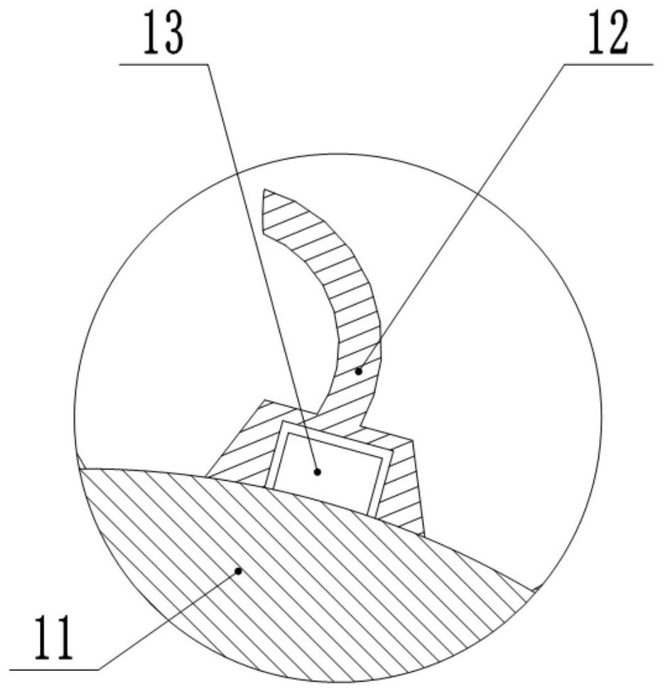
[0026] The crushed concrete and steel bars fall onto the first conveyor belt 6. During the process of the first conveyor belt 6 conveying the reinforced concrete mixture, the first cylinder and the second cylinder are activated by the PLC controller, and the first cylinder pushes the extrusion plate 9 to slide towards each other. , the extruding plate 9 drives the bending plate 10 to slide towards each other, and the steel bar is bent through the staggered extrusion between the bending plates 10 to facilitate the hooking of the hook claw 12 .

[0027] When the first conveyor belt 6 transports the steel ba...


PUM


Abstract

The invention relates to the field of building construction, and particularly discloses a reinforced concrete waste treatment device which comprises a crushing box. A coarse crusher is arranged in thecrushing box, an obliquely-arranged sliding way is fixed to the output end of the coarse crusher, and a crushing device is arranged at the lowest end of the sliding way and comprises two crushing rollers arranged in parallel; the crushing rollers are rotationally connected to the inner wall of the crushing box, the two crushing rollers rotate oppositely, a plurality of crushing thorns are distributed on the surfaces of the crushing rollers, and the crushing thorns of the adjacent crushing rollers are alternately distributed; a first conveying belt is fixed below the crushing rollers, a separation roller is arranged above the first conveying belt, the length of the separation roller is equal to the width of the first conveying belt, the separation roller is rotationally connected to the inner wall of the crushing box, and a plurality of staggered claws are fixed to the upper surface of the separation roller and make contact with the first conveying belt; and a second conveying belt which is obliquely arranged is fixed obliquely below the separation roller. The reinforced concrete waste treatment device aims to solve the problem of separation of steel bars and concrete in reinforcedconcrete waste.

Description

technical field [0001] The invention relates to the technical field of building construction, and specifically discloses a reinforced concrete waste treatment device. Background technique [0002] With the rapid development of my country's economy and the advancement of urbanization, the amount of construction waste generated and discharged is increasing rapidly. At present, the recycling rate of construction waste in my country is relatively low, especially that of reinforced concrete waste. At present, some of these construction wastes can only be dumped or landfilled, and cannot be well treated and comprehensively utilized, resulting in wasting resources, occupying land, polluting the environment, and affecting the coordinated development of people's lives and the ecological environment. [0003] The main load-bearing components of most buildings in our country are constructed with reinforced concrete structures. The reinforced concrete structure is a structure made of ...

Claims


Application Information

Patent Timeline
Patent Type & Authority Applications(China)
IPC IPC(8): B02C1/02B02C4/08B02C23/00B02C23/08B02C23/10B03C1/18B03C1/30B21F1/00
CPCB02C1/02B02C4/08B02C23/00B02C23/08B02C23/10B03C1/18B03C1/30B21F1/00
Inventor 汪小林曹文根朱利君张波马天雨赵宇超沈建华张英楠
Owner SHANGHAI NO 4 CONSTR
Why Eureka
Try Eureka