
Inert gas purification equipment and recovery and purification system

A technology of inert gas and purification equipment, applied in gas treatment, chemical instruments and methods, dispersed particle filtration, etc., can solve the problem that high-purity inert gas cannot be recycled and reused, manufacturers pay huge costs, and the price of high-purity inert gas Expensive and other problems, to achieve the effect of improving work efficiency and work quality, reducing purification operation costs, and excellent equipment structure

Inactive Publication Date: 2020-11-03
北京北氧特气工程技术有限公司
View PDF8 Cites 0 Cited by
  • Summary
  • Abstract
  • Description
  • Claims
  • Application Information

AI Technical Summary

Problems solved by technology

[0002] In the existing industrial production of the single crystal industry, the single crystal furnace needs to use a large amount of high-purity inert gas, such as argon, helium, etc. every day, and the high-purity inert gas itself is expensive. If the high-purity inert gas after use If it cannot be recycled and reused, the production enterprise not only needs to pay a huge cost, but also causes a waste of inert gas
The recovered inert gas needs to be re-purified, and it cannot be reused without re-purification.
[0003] For example, in the traditional gas purification technology, the argon tail gas discharged from the silicon core furnace is used as the raw material gas, which requires hydrodeoxygenation and purification through a cryogenic liquefaction process. It is difficult to avoid hydrogenation devices during the purification process, such as explosion-proof For the use of workshops and explosion-proof electrical equipment, the purification equipment covers a large area, and there are high safety risks in the purification process, and it is easy to cause the collapse of the tower due to the unbalanced flow rate of the recovered gas.

Method used


Image

  • Inert gas purification equipment and recovery and purification system
  • Inert gas purification equipment and recovery and purification system
  • Inert gas purification equipment and recovery and purification system

Examples


Embodiment Construction

[0061] Reference will now be made in detail to the exemplary embodiments, examples of which are illustrated in the accompanying drawings. When the following description refers to the accompanying drawings, the same numerals in different drawings refer to the same or similar elements unless otherwise indicated. The implementations described in the following exemplary examples do not represent all implementations consistent with the present invention. Rather, they are merely examples of apparatuses and methods consistent with aspects of the invention as recited in the appended claims.

[0062] The terminology used in the present invention is for the purpose of describing particular embodiments only and is not intended to limit the invention. As used herein and in the appended claims, the singular forms "a", "the", and "the" are intended to include the plural forms as well, unless the context clearly dictates otherwise. It should also be understood that the term "and / or" as use...


PUM


Abstract

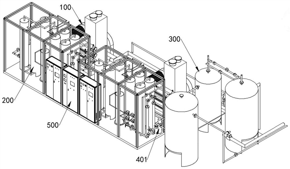
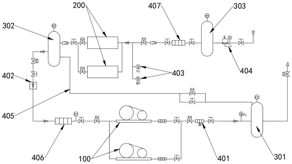
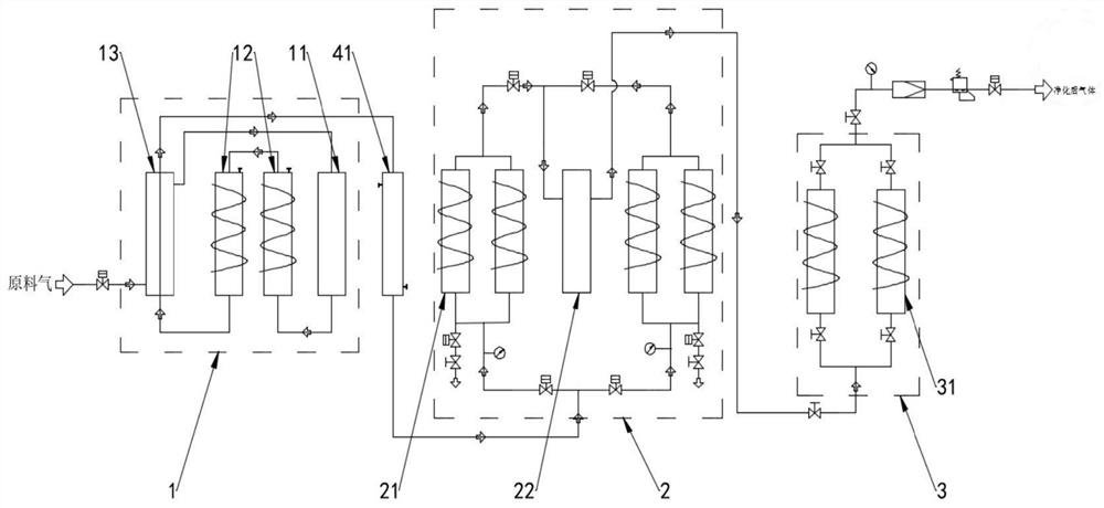
The invention provides inert gas purification equipment which comprises a first purification assembly, a second purification assembly and a third purification assembly, the first purification assembly, the second purification assembly and the third purification assembly are sequentially connected through pipelines, and electromagnetic valves are arranged on the pipelines. The first purification assembly is used for carrying out deoxidation and denitrification treatment on passing gas, the second purification assembly is used for carrying out dehydration, hydrocarbon removal, carbon monoxide removal and carbon dioxide removal treatment on the passing gas, and the third purification assembly is used for carrying out denitrification treatment on the passing gas. The invention further providesan inert gas recycling and purifying system. Three-stage impurity removal and purification treatment are carried out on passing gas, it is guaranteed that purified argon and helium meet the use requirement, the structure is simple, the occupied area of the equipment is small, operation and maintenance are easy and convenient, the purification process is shortened, and the purification efficiencyis improved.

Description

Technical field: [0001] The technical field of the present invention is the technical field of gas purification, and in particular relates to an inert gas purification equipment and recovery and purification system. Background technique: [0002] In the existing industrial production of the single crystal industry, the single crystal furnace needs to use a large amount of high-purity inert gas, such as argon, helium, etc. every day, and the high-purity inert gas itself is expensive. If the high-purity inert gas after use If it is not recycled and reused, the production enterprise not only needs to pay a huge cost, but also causes a waste of inert gas. The recovered inert gas needs to be purified again, and it cannot be reused without further purification. [0003] For example, in the traditional gas purification technology, the argon tail gas discharged from the silicon core furnace is used as the raw material gas, which needs to be purified by hydrodeoxygenation and cryoge...

Claims


Application Information

Patent Timeline
Patent Type & Authority Applications(China)
IPC IPC(8): B01D53/26B01D53/04B01D53/00B01D46/00
CPCB01D53/005B01D53/26B01D53/261B01D53/04B01D2257/102B01D2257/104B01D46/62Y02C20/40
Inventor 黄宝福宋兰芹饶勇平
Owner 北京北氧特气工程技术有限公司
Learn More