
Press-holding system and press-holding method

A valve and hand-held technology, applied in the field of medical devices, can solve problems such as inability to effectively protect the valve, failure to prevent valve rebound, and valve fracture

Active Publication Date: 2020-11-03
SHANGHAI NEWMED MEDICAL CO LTD
View PDF11 Cites 4 Cited by
  • Summary
  • Abstract
  • Description
  • Claims
  • Application Information

AI Technical Summary

Problems solved by technology

[0003] However, the existing valve crimping machine and crimping method cannot effectively protect the valve during the crimping process, which makes the valve easy to be broken when it is crimped; , can not prevent the valve from rebounding, because the outer diameter of the valve will increase after rebounding, which will bring risks to the operation

Method used


Image

  • Press-holding system and press-holding method
  • Press-holding system and press-holding method
  • Press-holding system and press-holding method

Examples


Embodiment 1

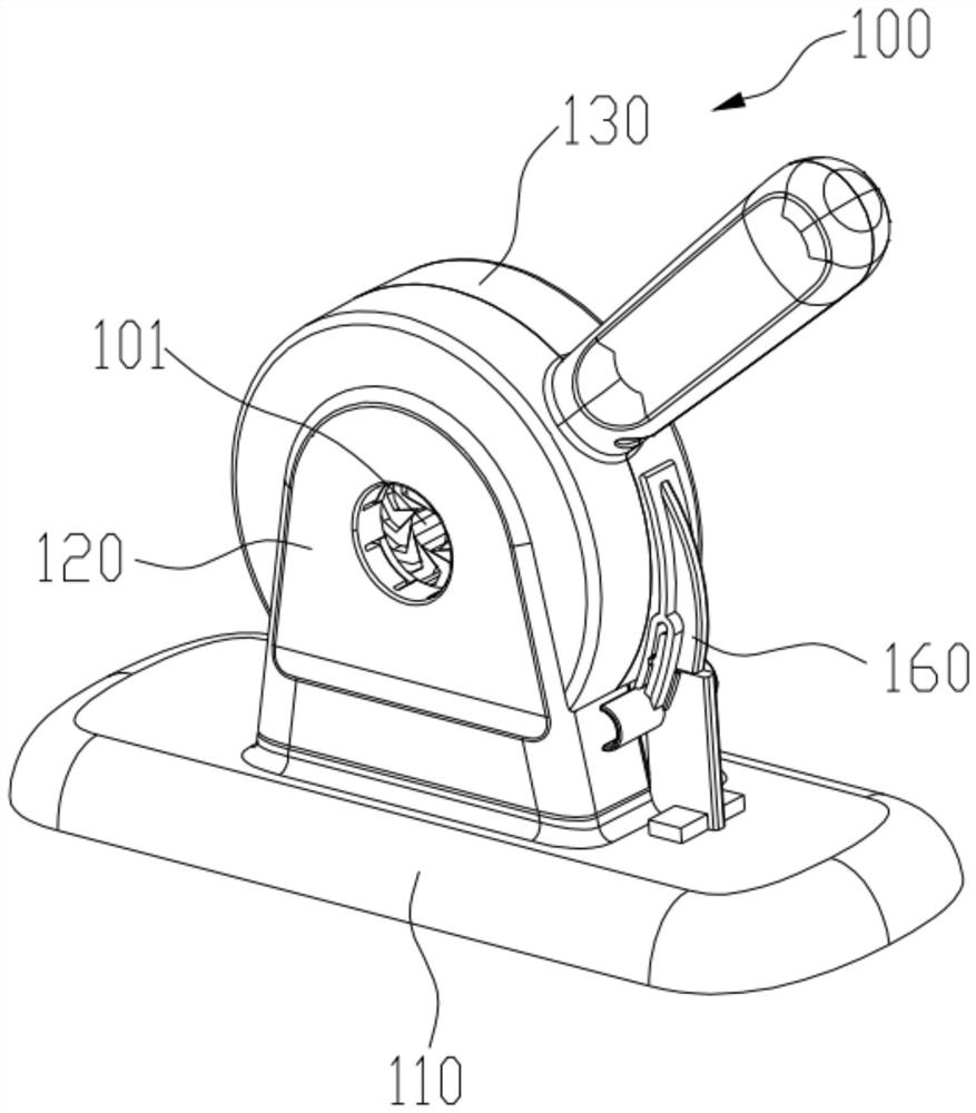
[0098] Such as Figure 1-Figure 20As shown, the present embodiment provides a valve crimping system for installing a valve on a delivery device for valve replacement surgery. The crimping system includes a valve crimping machine 100, a hand-held crimping device 200, a crimping sponge 300 and a crimping film 400, wherein the valve crimping machine 100 is used to crimp the valve in the first stage, and the hand-held crimping device 200 For the second stage of crimping the valve. The crimping sponge 300 is used in the first stage of crimping. The crimping sponge 300 has a cylindrical structure. A good valve and the crimping sponge 300 are placed on the designated position of the conveyor (i.e. Figure 20 The conveyer crimping section 600 shown in ), when crimping, put the assembled valve, crimping sponge 300 and the conveyor into the crimping port 101 of the valve crimping machine to pass through the valve crimping machine 100 pairs The valve undergoes the first stage of crimp...

Embodiment 2

[0127] This embodiment provides a crimping method, including a first-stage crimping and a second-stage crimping, wherein the first-stage crimping is used to crimp the valve through the valve crimping machine 100, and after crimping, it is used to prevent the valve from returning. In the second stage of crimping, the hand-held crimping device 200 is used to continuously crimp the valve until the operation begins, thereby improving the efficiency of the operation.

[0128] Specifically, the above-mentioned first-stage crimping includes:

[0129] S1. Soak the crimping sponge 300 in physiological saline for a first set time and then take it out. Preferably, the first set time is 3 minutes. In this embodiment, before crimping, the crimping sponge 300 is soaked in physiological saline for 3 minutes. During the first stage of crimping, the crimping sponge 300 will release the internal water when squeezed, thereby protecting the leaflets of the valve from Tear due to drying and stre...


PUM


Abstract

The invention relates to the technical field of medical instruments, and discloses a press-holding system and a press-holding method. The press-holding system comprises a valve press-holding machine,a handheld press-holding device, a conveyor, press-holding sponge and a press-holding film, wherein the valve press-holding machine is used for performing first-stage press-holding on a valve, and thehandheld press-holding device is used for performing second-stage press-holding on the valve; the press-holding sponge is used during first-stage press-holding, and adopts a cylindrical structure, and the valve is arranged in the press-holding sponge in a penetrating manner; and the press-holding film is used during second-stage press-holding, and adopts a cylindrical structure, the valve is arranged in the press-holding film in a penetrating manner after the first-stage press-holding is finished, and the handheld press-holding device is provided with a self-locking structure. According to the press-holding method, the valve press-holding machine is used for performing first-stage press-holding on the valve, and the handheld press-holding device is used for performing second-stage press-holding on the valve. The valve can be effectively prevented from being broken in the press-holding process, and the valve is prevented from rebounding after being pressed and held.

Description

technical field [0001] The invention relates to the technical field of medical devices, in particular to a crimping system and a crimping method. Background technique [0002] With the continuous expansion of the application range of the ball expander in heart valve replacement surgery, how to quickly and effectively install the ball expander on the conveyor for valve replacement surgery has become a problem that needs to be focused on at this stage. A valve crimping machine is one device used to address such problems. [0003] However, the existing valve crimping machines and crimping methods cannot effectively protect the valve during the crimping process, which makes the valve easy to be broken when it is crimped; , can not prevent the valve from rebounding, because the external diameter of the valve rebounds after the increase, which brings risks to the operation. [0004] Therefore, there is an urgent need for a crimping system and crimping method that can prevent val...

Claims


Application Information

Patent Timeline
IPC IPC(8): A61F2/24
CPCA61F2/24A61F2/2427A61F2/2415A61F2240/001
Inventor 王思维王海山虞奇峰秦涛
Owner SHANGHAI NEWMED MEDICAL CO LTD
Learn More