


Quick Research
Generate reliable direction feasibility study reports for your R&D in just a few steps.

Technical Q&A
Discover and master advanced knowledge NOW. Basics, ideas, possibilities, all at once.

Find Solutions
As an expert in R&D theories, this can generate solutions to your technical problems instantly.

Evaluate Feasibility
Analyze your overall solution with one click, know your potential R&D risks in advance.

Monitor Landscape
Get weekly tech updates, stay abreast of the latest tech innovations and key insights.
Automatic bowl support manufacturing equipment
A technology for manufacturing equipment and bowl holders, which is applied in the field of automatic bowl holder manufacturing equipment, can solve the problems of poor toughness and low efficiency of bowl holders, and achieve the effects of good toughness, improved efficiency, and improved stability
- Summary
- Abstract
- Description
- Claims
- Application Information
AI Technical Summary
Problems solved by technology
Method used
Image


Examples
Embodiment 1
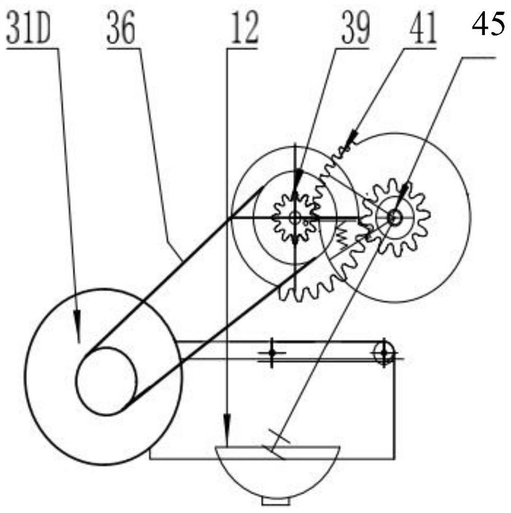
[0036] Such as Figure 1-7 As shown, an automatic bowl holder manufacturing equipment includes a support, a quantitative filling device for noodle sauce, a transmission transmission device, a stirring device, and a heating and steaming device; the transmission transmission device includes a horizontal car 13, two transmission transmission chains and multiple A driven wheel, a plurality of driven wheels are all installed on the support, and the horizontal car 13 is movably installed in the middle of two conveying transmission chains, and the two conveying chains are ring chains, and the two conveying chains rotate synchronously. The driven sprocket is folded to form a circular and rotatable chain structure; a porcelain bowl 12 is placed on the horizontal car 13, and the horizontal car 13 is driven by the driving device through two conveying transmission chains in the noodle sauce quantitative filling device, stirring device, heating The steaming devices are circulated sequentia...
Embodiment 2
[0054] The application of this device in specific production is as follows:
[0055] Add a small amount of water through the water pipe 1, pour the noodle sauce into the feed hopper 2, and enter the noodle sauce bucket 4 through the spiral stirring filter 3; the water pump 5 pumps out the noodle sauce in the noodle sauce bucket 4 and enters the noodle sauce funnel 7 through the noodle sauce input pipe 6; At this time, the quantitative controller 10 controls the rotary pneumatic valve 9, so that the noodle sauce is quantitatively poured into the porcelain bowl 12 placed on the horizontal car 13 through the noodle sauce into the bowl pipe 11;
[0056] The area near the outlet heating pipe 72 in the heating and steaming device is defined as the middle temperature area, and the area near the high-temperature steam pipe 63 in the heating and cooking device is defined as the high temperature area;
[0057] The continuous operation of the conveying transmission drives the horizontal ...
PUM
 Abstract
Description
Claims
Application Information
 - R&D Engineer
- R&D Manager
- IP Professional
- Industry Leading Data Capabilities
- Powerful AI technology
- Patent DNA Extraction
Browse by: Latest US Patents, China's latest patents, Technical Efficacy Thesaurus, Application Domain, Technology Topic, Popular Technical Reports.
© 2024 PatSnap. All rights reserved.Legal|Privacy policy|Modern Slavery Act Transparency Statement|Sitemap|About US| Contact US: help@patsnap.com