Sensor device

A technology of sensor equipment and optical detectors, applied in the direction of sensors, optical sensors, gymnastics equipment, etc., can solve the problems of weak signal superposition and interference, and achieve improved coupling output, improved quality or signal-to-noise ratio, and improved beam shaping Effect

Pending Publication Date: 2020-10-30
OSRAM OLED
View PDF5 Cites 0 Cited by
  • Summary
  • Abstract
  • Description
  • Claims
  • Application Information

AI Technical Summary

Problems solved by technology

However, the signal measured here can be weak and superimposed with interference

Method used


Image

  • Sensor device
  • Sensor device
  • Sensor device

Examples


Embodiment Construction

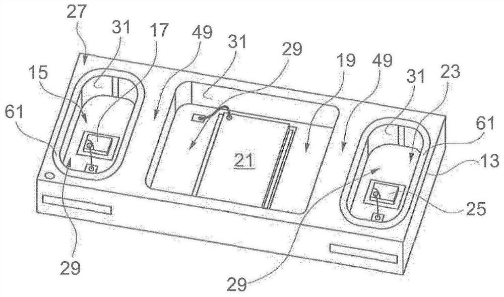
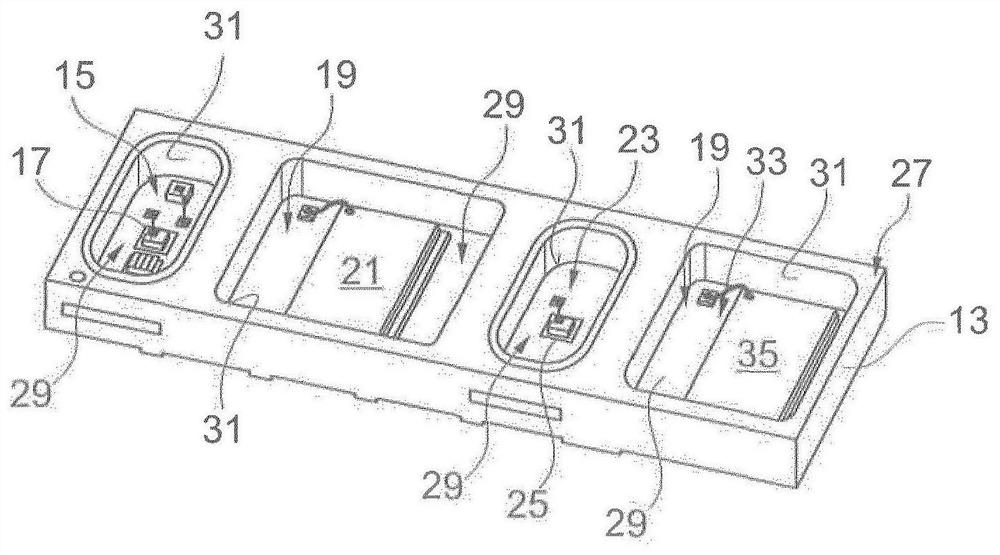
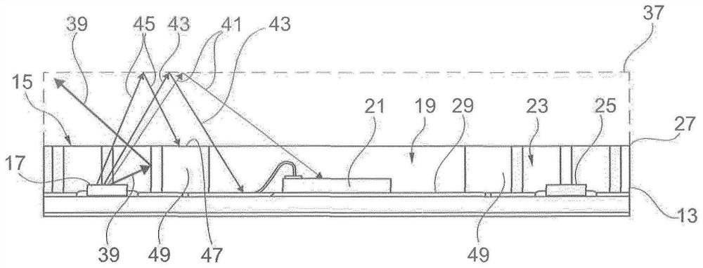
[0046] exist figure 1 The sensor device shown in is especially designed to measure at least one vital parameter of a human body. A first cavity 15 is formed in the housing 13 of the sensor device, in which a first light emitter 17 is arranged. The housing 13 also has a second cavity 19 in which a first light detector 21 is arranged. The housing 13 comprises a third cavity 23 in which a second light emitter 25 is arranged. Such as figure 1 As shown, the second cavity 19 with the first light detector 21 is arranged between the two cavities 15 , 23 with the light emitters 17 , 25 . Here, the cavities 15 , 19 , 23 are separated from one another by respective partition walls 49 .

[0047] Each of the cavities 15 , 19 and 23 has an opening on the bottom side 27 of the housing 13 . Thus, each of the cavities 15 , 19 and 23 is open to the bottom side 27 of the housing 13 . Light can thus be emitted from the respective cavity 15 , 19 , 23 to the outside or into the respective cav...


PUM


Abstract

A sensor device, in particular for measuring at least one vital sign of the human body, comprises a housing having at least one first and second cavity, wherein: at least one light emitter is positioned in the first cavity and at least one light detector is positioned in the second cavity; each of the cavities has an opening on the underside of the housing so that light can pass out of each cavityto the exterior and / or can enter each cavity from the exterior; and each of the cavities has a base lying opposite the underside of the housing, and has a peripheral lateral wall extending between the base and the underside of the housing. Said device is characterized in that the base and / or the lateral wall of the first cavity is a different color than the base and / or the lateral wall of the second cavity in order to achieve a greater reflectivity in the first cavity than in the second cavity.

Description

[0001] This application claims priority from German patent application DE 102018105904.3, the disclosure content of which is hereby incorporated in this application. technical field [0002] The invention relates to a sensor device, in particular for measuring at least one vital parameter of a human body, having a housing with at least a first cavity and a second cavity, wherein at least one light emitter is arranged in the first cavity, and wherein at least one photodetector is arranged in the second cavity, wherein each of the cavities has an opening on the bottom side of the housing so that light can be emitted from the corresponding cavity to the outside and and / or inject from the outside into corresponding cavities, wherein each of the cavities has a bottom opposite the bottom side of the housing, and a surrounding side extending between the bottom and the bottom side of the housing wall. Background technique [0003] Such a sensor device is known from DE 10 2016 105 8...

Claims


Application Information

Patent Timeline
Patent Type & Authority Applications(China)
IPC IPC(8): A61B5/024A61B5/00
CPCA61B5/02427A61B5/02438A61B5/681A61B5/6824A61B2503/10A61B2560/0406A61B2560/0462A61B2562/0233A61B2562/168A61B2562/185A61B5/0059A61B5/02416A63B24/0062
Inventor 法伊纳·埃塞尔克劳斯·耶格斯特凡·哈斯尔贝克
Owner OSRAM OLED
Why Eureka
Try Eureka