Circulating fluidized bed catalytic combustion method for treating organic waste gas
A circulating fluidized bed, catalytic combustion technology, applied in the direction of combustion method, combustion type, incinerator, etc., can solve the problems of complex system structure and operation
- Summary
- Abstract
- Description
- Claims
- Application Information
AI Technical Summary
Problems solved by technology
Method used
Image
Examples
Embodiment 1
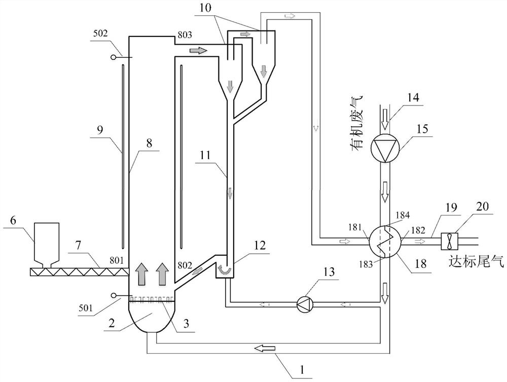
[0048] Such as figure 1 A circulating fluidized bed catalytic combustion system 1 for treating organic waste gas shown, the system includes:
[0049] A circulating fluidized bed catalytic combustion furnace, the circulating fluidized bed catalytic combustion furnace includes a fluidization air chamber 2, an air distribution plate 3, a riser 8, a separator 10 and a dipleg 11, wherein the upper part of the riser 8 is The feed port 803 is connected to the feed port of the separator 10, the lower discharge port of the separator 10 is connected to the upper end feed port of the material leg 11, and the lower end discharge port of the material leg 11 is connected to the riser return pipe 802, and the circulation Insulation of the whole circuit of the fluidized bed catalytic combustion furnace;
[0050] The heat recovery and heating device, the heat recovery and heating device includes a heat exchanger 18 and an electric heating component 9, wherein the heat exchanger 18 is a partit...
Embodiment 2
[0065] Such as figure 2 shown in figure 1 Based on the illustrated circulating fluidized bed catalytic combustion system for treating organic waste gas, an improved circulating fluidized bed catalytic combustion system for treating organic waste gas II is also provided. In addition to the components in system one, system two also includes a return device, also known as a particle circulation control device, whose function is not only to adjust and control the particle circulation to achieve the required particle circulation rate; "Backchannel" flow to separator 10. The material return device includes a material return valve 12, a material return air booster fan 13 and a corresponding connecting air duct, wherein the material return valve 21 is between the material outlet at the lower end of the material leg 11 and the inlet of the riser return material pipe 802, and A branch pipe is branched out from the riser inlet main pipe 1 and connected with the air inlet of the return...
Embodiment 3
[0069] Such as image 3 shown in figure 2 Based on the illustrated circulating fluidized bed catalytic combustion system for treating organic waste gas, an improved circulating fluidized bed catalytic combustion system for treating organic waste gas is also provided III. In addition to the components in system two, system three also includes silo 6, high-pressure screw feeder 7, lower pressure measuring point 501, upper pressure measuring point 502, and a high-pressure screw is provided at the feed port 801 of the front wall of the riser 8. The feeder 7 and the high-pressure screw feeder 7 are arranged below the silo 6 , the lower pressure measuring point 501 is arranged on the upper side of the air distribution plate 3 , and the upper pressure measuring point 502 is arranged on the top of the cavity of the riser 8 .
[0070] In this embodiment, a circulating fluidized bed catalytic combustion method for treating organic waste gas based on system 3, in addition to the steps ...
PUM
 Abstract
Description
Claims
Application Information
 - R&D
- Intellectual Property
- Life Sciences
- Materials
- Tech Scout
- Unparalleled Data Quality
- Higher Quality Content
- 60% Fewer Hallucinations
Browse by: Latest US Patents, China's latest patents, Technical Efficacy Thesaurus, Application Domain, Technology Topic, Popular Technical Reports.
© 2025 PatSnap. All rights reserved.Legal|Privacy policy|Modern Slavery Act Transparency Statement|Sitemap|About US| Contact US: help@patsnap.com


