Switchable rapid interval barring gear device

A turning device and fast technology, applied in the direction of fluid pressure actuators, engine components, machines/engines, etc., can solve problems such as shrinking, sealing structure failure, and accelerated aging of sealing rings

Pending Publication Date: 2020-10-30
新疆新业能源化工有限责任公司
View PDF1 Cites 2 Cited by
  • Summary
  • Abstract
  • Description
  • Claims
  • Application Information

AI Technical Summary

Problems solved by technology

However, this device does not take into account that the spring force will become smaller after a period of use, which will easily cause the cranking hook to slip.
[0005] In addition, the hydraulic device of the existing hydraulic barring mechanism has a set of oil outlet pipeline and oil inlet pipeline, and the piston completes a reciprocating cycle by its own gravity during the downward process, resulting in a certain delay in the control cycle
Moreover, the piston and its piston rod of the hydraulic barring mechanism are sealed with multi-layer O-rings. Due to the limited number of sealing rings added, the oil storage area is small, and the aging of the sealing rings is accelerated during the rapid movement of the piston up and down, making the Seal structure failure

Method used


Image

  • Switchable rapid interval barring gear device
  • Switchable rapid interval barring gear device
  • Switchable rapid interval barring gear device

Examples


Embodiment 1

[0031] Hydraulic cranking method

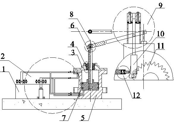
[0032] Such as figure 1 , figure 2 , image 3 , Figure 4 , Figure 5 , Image 6 , Figure 7 A switchable fast intermittent cranking device is shown, including: fuel tank 1, fast control oil circuit system 2, hydraulic cylinder cover 3, decompression and dust-proof sealing assembly 4, hydraulic cylinder body 5, piston rod 6, piston Sealing assembly 7, detachable connecting piece 8, transmission rod assembly 9, barring hook 10, barring ratchet 11, hook angle self-adjusting mechanism 12.

[0033] The oil tank 1 is connected with the rapid control oil circuit system 2, the oil tank 1 supplies oil for the rapid control oil circuit system 2, and the return oil generated by the rapid control oil circuit system 2 is returned to the Fuel tank 1, the other side of the rapid control oil circuit system 2 is connected to the hydraulic cylinder block 5; the upper end of the hydraulic cylinder block 5 is provided with a hydraulic cylinder cover 3, ...

Embodiment 2

[0038] Manual cranking method

[0039] When the hydraulic cranking system fails, it needs to be converted to manual cranking. The manual cranking mode is different from the hydraulic cranking mode except that the power source is different. The connection mode between the mechanisms 12 is exactly the same as the hydraulic cranking mode, and will not be repeated in this embodiment; the difference is that when the hydraulic cranking system fails, only the detachable screw 812 needs to be removed to realize the pressure rod 911 Disengagement with the piston rod 6 is realized by manual cranking by manually shaking the depression bar 911 up and down.


PUM


Abstract

The invention discloses a switchable rapid interval barring gear device. A hydraulic barring gear and a manual barring gear are combined, the switchable rapid interval barring gear device is characterized in that switching of operation of the hydraulic barring gear and the manual barring gear is utilized, rotation of a ratchet wheel is achieved through only one barring gear hook, by means of a hook angle self-adjusting mechanism, the hook can be adjusted at a certain angle, and the possibility that the turning gear slips is avoided. According to the switchable rapid interval barring gear device, a double-oil-way rapid oil control system is arranged, so that the movement of a rod piece is controlled more autonomously and rapidly, multi-layer O-shaped sealing rings are sealed and improved into an integral sealing device, the oil carrying frequency is higher, uninstalling is more convenient, and dust prevention and pressure reduction are achieved.

Description

technical field [0001] The invention relates to the field of turbomachinery barring, in particular to a switchable fast intermittent barring device. Background technique [0002] Barring is the main equipment to eliminate the thermal bending of the rotor before the turbine is run and after the shutdown. Before the turbine rotor spins and during the shutdown of the unit, the rotor of the barring device stops rotating, and the rotor will be thermally bent. In this case, if the turbomachinery is restarted, it will cause a scuffing failure. In order to avoid such accidents, the turbomachinery is equipped with a cranking device. [0003] In order to solve the problem of thermal bending of the steam turbine after the rotor stops rotating, the application number is 201120452299.6 discloses a hydraulic barring device, using two independent modules of the hydraulic mechanism and the manual mechanism to realize two ways of barring control, but the The equipment does not take into a...

Claims


Application Information

Patent Timeline
IPC IPC(8): F01D25/34F15B15/14F15B15/20
CPCF01D25/34F15B15/14F15B15/1442F15B15/1452F15B15/20
Inventor 李鑫焦金峰赵志强万学帮田以海赵峰邵鹏程王江辉
Owner 新疆新业能源化工有限责任公司
Why Eureka
Try Eureka