
Composite non-bonding flexible pipe, preparation method and application

A reinforced composite material, non-bonding technology, applied in the field of flexible pipes, can solve the problems such as the gap control of the spirally wound strip of the bearing layer, and achieve the effect of improving the bearing capacity of internal pressure

Inactive Publication Date: 2020-10-30
CHINA UNIV OF PETROLEUM (EAST CHINA) +1
View PDF8 Cites 0 Cited by
  • Summary
  • Abstract
  • Description
  • Claims
  • Application Information

AI Technical Summary

Problems solved by technology

[0006] The inventors found that the fiber-reinforced composite material flexible pipe in the prior art has two or more layers of wear-resistant layers between the helically wound load-bearing layers. Although the friction between the load-bearing layers is reduced, it still cannot solve the problem of the load-bearing layer. Problems with Gap Control Between Helically Wound Strips

Method used


Image

  • Composite non-bonding flexible pipe, preparation method and application
  • Composite non-bonding flexible pipe, preparation method and application
  • Composite non-bonding flexible pipe, preparation method and application

Examples


preparation example Construction

[0056] In the second aspect, the preparation method of the above-mentioned non-adhesive composite flexible pipe, the specific steps of the preparation method are:

[0057] The hot melt adhesive layer and the first elastic material layer are coated on the outer sidewall of the inner liner by means of a multi-layer co-extruded inner tube;

[0058] Wrapping the compression-resistant layer on the outer surface of the first elastic material layer by means of interference fit;

[0059] A second elastic material layer is arranged on the outer surface of the pressure-resistant layer by heating and extruding;

[0060] Then repeat the setting of the elastic material layer and the compression layer;

[0061] wrapping the tensile layer around the outer surface of the compression layer;

[0062] The outer protection layer is arranged on the outside of the tensile layer by extrusion molding.

[0063] In the third aspect, the above-mentioned non-adhesive flexible pipe of composite materia...

Embodiment 1

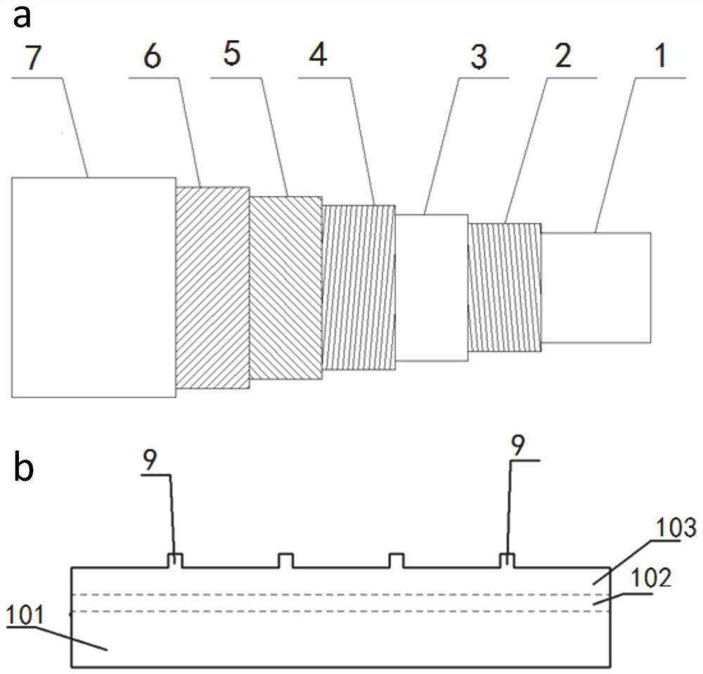
[0066] Such as figure 1 As shown in a, the flexible pipe from inside to outside is the lining pipe layer 1, the first compression layer 2, the second elastic material layer 3, the second compression layer 4, the first tensile layer 5, and the second anti-tension layer. Pull layer 6, outer protection layer 7. Such as figure 1 As shown in b, the inner liner layer includes an inner liner 101 , a hot melt adhesive layer 102 , and a first elastic material layer 103 from inside to outside.

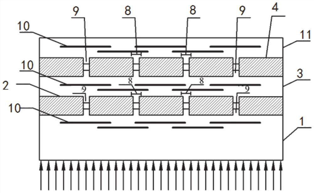
[0067] Such as figure 1 As shown in b, the first elastic material layer 103 is used as a gap control layer, and the first elastic material layer 103, the hot melt adhesive layer 102, and the inner liner 101 are combined by hot extrusion. The first compression layer 2 is spirally wound on the outer surface of the first elastic material layer 103, the second elastic material layer 3 is arranged on the first compression layer 2 by heating extrusion molding, and then the second compression layer ...

Embodiment 2

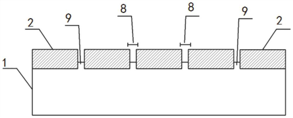
[0071] Such as figure 2 As shown, compared to Example 1, the structure and distribution of the flexible tube is different. The flexible pipe is provided with an inner liner layer 1 and a first compression layer 2, and a tensile layer and an outer protective layer are arranged on the outside of the first compression layer 2. The inner liner layer includes an inner liner, a hot melt adhesive layer and a first elastic material layer from inside to outside.

[0072] The first elastic material layer is used as the gap control layer. The combination of the first elastic material layer, the inner liner pipe and the hot melt adhesive layer is the same as that in Example 1. The position of the first elastic material layer relative to the gap between the first compression layer 2 The protrusions enter the gaps 8 of the pressure-resistant layer to form fillers 9 .

[0073] The elastic material layer is made of propylene-based elastomer. The compression layer is a helically wound cont...


PUM

PropertyMeasurementUnit
Winding angleaaaaaaaaaa
Thicknessaaaaaaaaaa
Winding angleaaaaaaaaaa

Abstract

The invention relates to a composite non-bonding flexible pipe, a preparation method and application. The flexible pipe comprises a lining pipe, a hot-melting layer, elastic material layers, compressive layers and tensile layers, wherein the number of the elastic material layers, the compressive layers and the tensile layers is one or more, the compressive layers are spiral winding belts, the adjacent winding belts of the compressive layers form a plurality of gaps, the elastic material layers are located between the lining pipe and the compressive layers or between the compressive layers andthe tensile layers or between the adjacent compressive layers, and bulges are formed on the portions, opposite to the gaps of the compressive layers, of the elastic material layers and enter the gapsof the compressive layers. According to the flexible pipe, the elastic material layers are gap control layers, fillers are formed in the gaps of the compressive layers, sliding of the adjacent windingbelts of the compressive layers or movement relative to the lining pipe is prevented beneficially, and perforating and thinning of the lining pipe can be prevented to a certain extent. Meanwhile, theelastic material layers have an anti-wear function, so that wear between the compressive layers, the tensile layers and the adjacent spiral winding belts is reduced.

Description

technical field [0001] The invention belongs to the technical field of flexible pipes, and in particular relates to a composite material non-adhesive flexible pipe, a preparation method and an application. Background technique [0002] The information disclosed in this background section is only intended to increase the understanding of the general background of the present invention, and is not necessarily taken as an acknowledgment or any form of suggestion that the information constitutes the prior art already known to those skilled in the art. [0003] With the development of oil and gas exploitation on land, the development of offshore oil and gas resources has been receiving more and more attention. At the same time, the demand for offshore oil and gas pipelines has also greatly increased. Compared with traditional rigid metal pipes, flexible pipes have good flexibility, can withstand large deformation, are easy to transport and install, and have good application prosp...

Claims


Application Information

Patent Timeline
IPC IPC(8): B29C48/21B29C48/10B29C48/49F16L11/02F16L11/04F16L11/14F16L11/16
CPCB29C48/10B29C48/21B29C48/49F16L11/02F16L11/04F16L11/14F16L11/16
Inventor 时晨王宏伟王森蔺全智慈胜宗王晓欣
Owner CHINA UNIV OF PETROLEUM (EAST CHINA)
Learn More