Shearing knife structure for tire

A technology of wool knives and tires, which is applied in the field of tire processing, can solve the problems of shearing knives affecting production efficiency, etc., and achieve the effect of improving the effect, avoiding damage, and avoiding shutdown and replacement

Inactive Publication Date: 2020-10-30
MAANSHAN WEILIJIAN MACHINERY TECH CO LTD
View PDF7 Cites 1 Cited by
  • Summary
  • Abstract
  • Description
  • Claims
  • Application Information

AI Technical Summary

Problems solved by technology

[0005] Aiming at the deficiencies of the prior art, the present invention provides a tire shearing knife structure, which solves the problem that the existing shearing knife needs to be stopped for replacement after wear and tear, which affects production efficiency

Method used


Image

  • Shearing knife structure for tire
  • Shearing knife structure for tire
  • Shearing knife structure for tire

Examples


Embodiment Construction

[0022] The following will clearly and completely describe the technical solutions in the embodiments of the present invention with reference to the accompanying drawings in the embodiments of the present invention. Obviously, the described embodiments are only some, not all, embodiments of the present invention. Based on the embodiments of the present invention, all other embodiments obtained by persons of ordinary skill in the art without making creative efforts belong to the protection scope of the present invention.

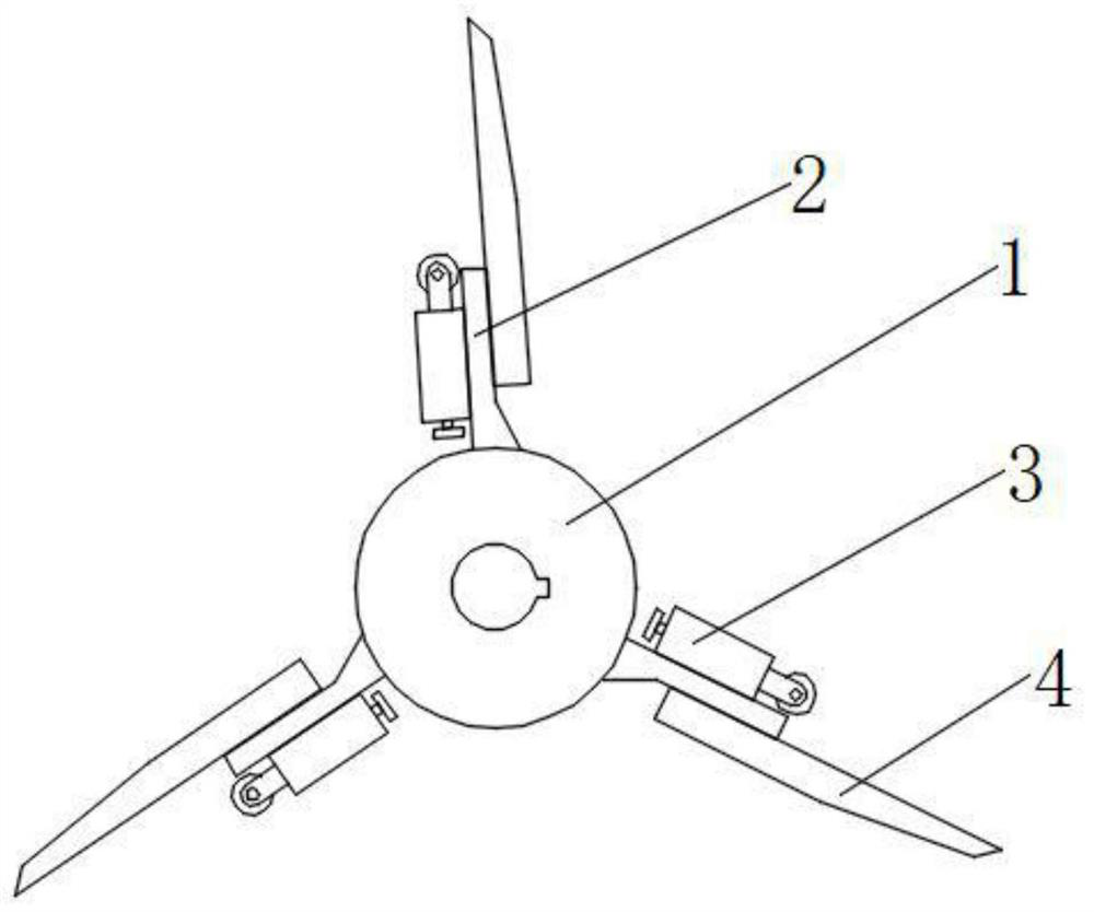
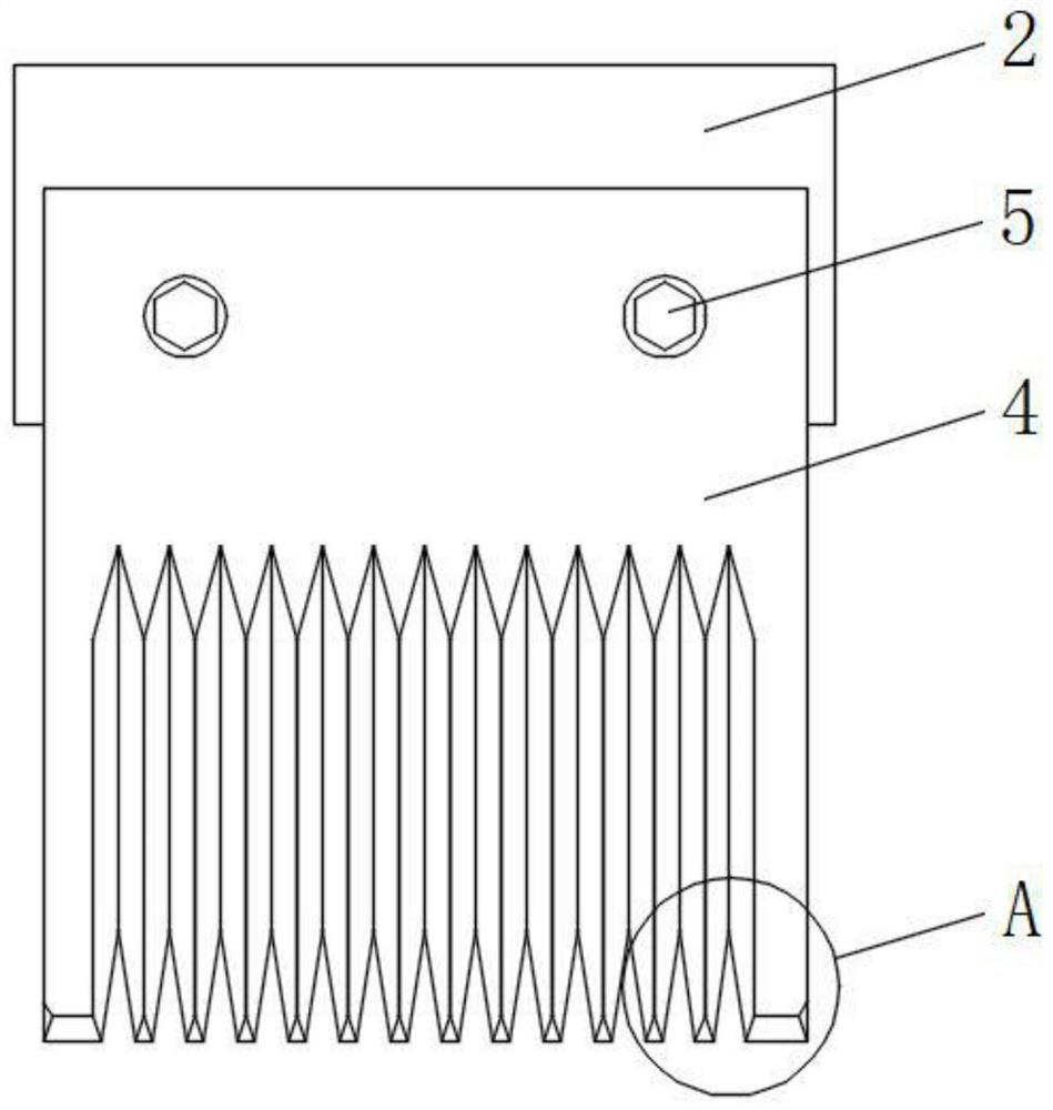
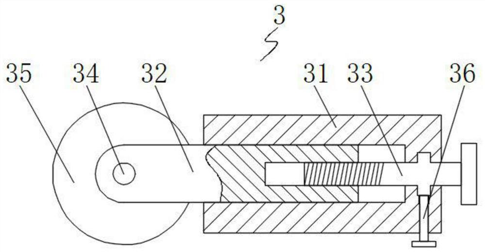
[0023] see Figure 1-5 , the present invention provides a technical solution: a tire shearing knife structure, including a drum 1, the surface of the drum 1 is fixedly connected with a mounting plate 2, there are three mounting plates 2 and are evenly distributed on the surface of the drum 1, the mounting plate 2 One side is fixedly connected with an adjustment device 3, and the other side of the mounting plate 2 is provided with a shearing knife 4, and the sh...


PUM

PropertyMeasurementUnit
angleaaaaaaaaaa

Abstract

The invention discloses a shearing knife structure for a tire. The shearing knife structure for the tire comprises a roller, wherein the surface of the roller is fixedly connected with three mountingplates, the mounting plates are uniformly distributed on the surface of the roller, one side of each mounting plate is fixedly connected with an adjusting device, the other side of each mounting plateis provided with a shearing knife, the shearing knives and the mounting plates are fixed through bolts, the surface of each shearing knife is provided with a V-shaped groove, one side of each V-shaped groove is provided with a first cutting edge, and the end, close to the cutting edge, of each shearing knife is provided with a second cutting edge. The invention relates to the technical field of tire processing. The shearing knife structure for the tire solves the problem that when an existing shearing knife is abraded, a machine needs to be shut down, and the production efficiency is affected.

Description

technical field [0001] The invention relates to the technical field of tire processing, in particular to a tire shearing knife structure. Background technique [0002] The tire shearing knife is a tool used in the last appearance inspection process in the tire manufacturing process. Its function is to remove the "hair" produced on the tire after the vulcanization process. Tires are processed by molds, and there are many small holes for exhaust on the molds. After the tires are molded and pressurized, after a period of heating and vulcanization, the tire rubber will slow down with the increase of temperature and time. When the temperature reaches the viscous flow temperature of the rubber, the rubber will have a certain kinetic energy to flow. At this time, some rubber will flow out from the vent hole on the mold. When the vulcanization is completed, the rubber solidifies and forms a " Yarn". After the vulcanization is completed, the last process of tire production is exter...

Claims


Application Information

Patent Timeline
Patent Type & Authority Applications(China)
IPC IPC(8): B26D7/26B29C37/02B26D1/28B29L30/00
CPCB26D1/0006B26D1/28B26D7/2614B26D7/2628B26D2001/0033B26D2001/0053B29C37/02B29L2030/00
Inventor 周煜
Owner MAANSHAN WEILIJIAN MACHINERY TECH CO LTD
Why Eureka
Try Eureka