
Periodic radial symmetry for filter pleating

A technology of filter and filter medium, which is applied in the direction of membrane filter, fixed filter element filter, filtration and separation, etc.

Active Publication Date: 2020-10-27
DONALDSON CO INC
View PDF6 Cites 0 Cited by
  • Summary
  • Abstract
  • Description
  • Claims
  • Application Information

AI Technical Summary

Problems solved by technology

One challenge with this arrangement is that the shorter pleats tend to migrate towards the central core area, or otherwise move away from the configuration in which the filter was originally manufactured

Method used


Image

  • Periodic radial symmetry for filter pleating
  • Periodic radial symmetry for filter pleating
  • Periodic radial symmetry for filter pleating

Examples


Embodiment Construction

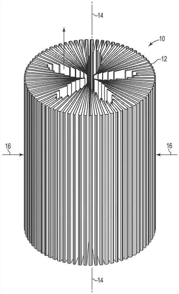
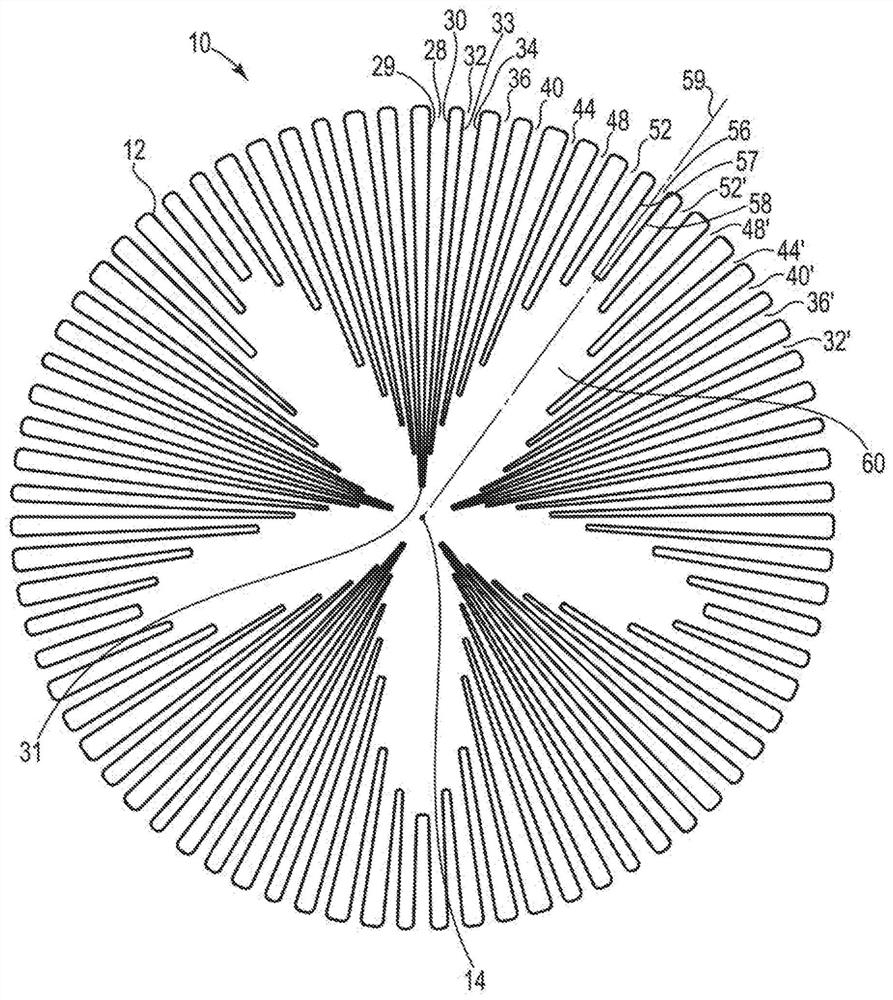
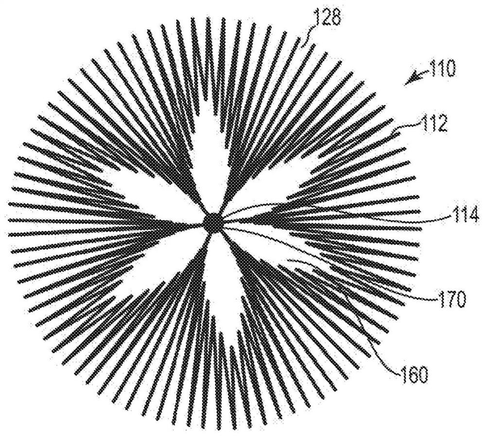
[0023] Referring now to the drawings, in which like reference numerals are used to label parts throughout the several figures, and first to figure 1 , shows a perspective view of a cylindrical filter 10 of the present invention, with arrows showing an exemplary direction of fluid flow during the filtration process. As shown, filter 10 includes pleated filter material 12 arranged in a cylindrical configuration about a central longitudinal axis 14, wherein the material includes pleats of varying lengths arranged in a pattern that repeats a certain number of times around its circumference. In this embodiment, fluid enters through the sides or outer perimeter of the filter 10, as indicated by arrow 16, and exits through a plurality of openings (which will be described below) in the direction generally indicated by arrow 18. Alternatively, the fluid may be directed in a direction opposite to that shown, and / or the fluid may move toward and / or away from the filter at angles other t...


PUM


Abstract

A cylindrical filter element having a central longitudinal axis and filter media including a plurality of radially extending pleats arranged in a pattern that repeats around the central longitudinal axis. Each of the pleats comprises an inner pleat tip, wherein the inner pleat tips of each pattern define an open area that extends along a height of the filter element, and wherein each pattern of pleats comprises a first series of intermediate pleats that descends in length from a major pleat to a minor pleat and a second series of intermediate pleats that ascends in length from the minor pleatto a major pleat of an adjacent pattern of pleats.

Description

[0001] Cross References to Related Applications [0002] This application claims priority and benefit to U.S. Provisional Patent Application No. 62 / 598,692, filed December 14, 2017, the entire contents of which are hereby incorporated by reference in their entirety. technical field [0003] The present invention relates to filters, and more particularly to pleated filter elements arranged in a cylindrical configuration for filter assemblies. Background technique [0004] Fluid filters are commonly used to remove contaminants from liquids or gases to prevent damage to downstream components such as engines. Filtration systems are generally configured such that incoming contaminated fluid travels along a flow path until it encounters the filter material. As the fluid passes through the filter material, a sufficient amount of contaminants will be captured by the filter material such that the fluid exiting the filter is considered clean enough for the resulting fluid's particul...

Claims


Application Information

Patent Timeline
Patent Type & Authority Applications(China)
IPC IPC(8): B01D46/24B01D46/52B01D29/21B01D29/23
CPCB01D46/2411B01D46/522B01D29/21B01D29/232B01D2201/122B01D2201/291B01D46/523B01D2201/127B01D2265/06
Inventor J·C·萨瓦斯若姆
Owner DONALDSON CO INC
Learn More