
Periodic radial symmetry for filter pleating

A technology of filter and filter medium, which is applied in the direction of membrane filter, fixed filter element filter, filtration and separation, etc.

Active Publication Date: 2022-04-19
DONALDSON CO INC
View PDF6 Cites 0 Cited by
  • Summary
  • Abstract
  • Description
  • Claims
  • Application Information

AI Technical Summary

Problems solved by technology

One challenge with this arrangement is that the shorter pleats tend to migrate towards the central core area, or otherwise move away from the configuration in which the filter was originally manufactured

Method used


Image

  • Periodic radial symmetry for filter pleating
  • Periodic radial symmetry for filter pleating
  • Periodic radial symmetry for filter pleating

Examples


Embodiment Construction

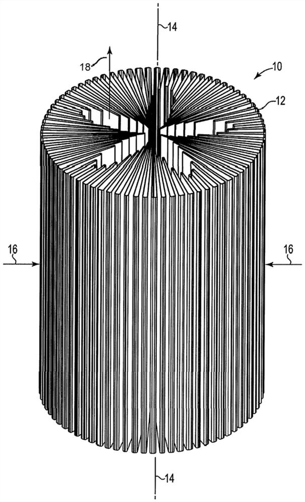
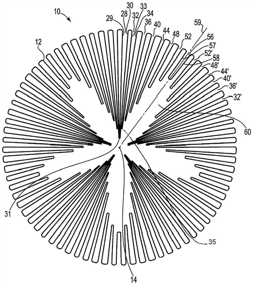
[0023] Referring now to the drawings, wherein, throughout several drawings, the component is marked with similar reference numerals, and reference is made first Figure 1 , shows a perspective view of the cylindrical filter 10 of the present invention, and an exemplary direction of fluid flow during the filtration process is shown with arrows. As shown, the filter 10 includes a pleated filter material 12 arranged in a cylindrical configuration around the central longitudinal axis 14, wherein the material comprises a fold of different lengths, to repeat a certain number of times around its circumference of the pattern is arranged. In the present embodiment, the fluid enters through the side or outer periphery of the filter 10, as indicated by the arrow 16, and through a plurality of openings (which will be described below) in the direction indicated by the arrow 18 to leave. Alternatively, the fluid may be guided in the opposite direction of the direction shown, and / or the fluid m...


PUM


Abstract

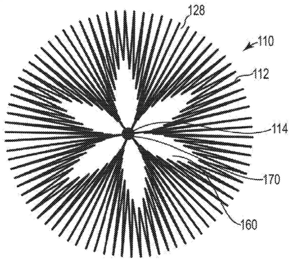
A cylindrical filter element is disclosed having a central longitudinal axis and a filter medium comprising a plurality of radially extending pleats arranged in a repeating pattern about the central longitudinal axis. Each of the pleats includes a pleat inner end, wherein each pattern of pleat inner ends defines an open area extending along the height of the filter element, and wherein each pleat pattern includes a pleat descending in length from a primary pleat to a secondary pleat A first series of intermediate pleats and a second series of intermediate pleats ascending in length from adjacent pleat pattern minor pleats to major pleats.

Description

[0001] Cross-references to relevant applications [0002] This application claims priority and interest in U.S. Provisional Patent Application No. 62 / 598,692 filed on December 14, 2017, the entire contents of the said documentation are incorporated herein by reference in its entirety. Technical field [0003] The present invention relates to a filter, and more particularly relates to a filter element arranged in a cylindrical configuration for pleated filter assemblies. Background [0004] Fluid filters are often used to remove contaminants from liquids or gases to prevent damage to downstream components such as engines. The filtration system is generally constructed so that the contaminated fluid enters moves along the flow path until it encounters the filter material. As the fluid passes through the filter material, a sufficient amount of contaminants will be captured by the filter material, making the fluid leaving the filter considered clean enough for the specific use of ...

Claims


Application Information

Patent Timeline
Patent Type & Authority Patents(China)
IPC IPC(8): B01D46/24B01D46/52B01D29/21B01D29/23
CPCB01D46/2411B01D46/522B01D29/21B01D29/232B01D2201/122B01D2201/291B01D46/523B01D2201/127B01D2265/06
Inventor J·C·萨瓦斯若姆
Owner DONALDSON CO INC
Learn More