Switching method applied to charging module transformer winding switching device

A transformer winding and switching device technology, which is applied in the direction of output power conversion devices, charging stations, and adjustment of electrical variables, etc. It can solve problems such as the inability to achieve seamless switching, the disconnection of transformer output current loops, and the difficulty in meeting full power output.

Inactive Publication Date: 2020-10-27
QINGDAO TOPSCOMM COMM +1
View PDF7 Cites 1 Cited by
  • Summary
  • Abstract
  • Description
  • Claims
  • Application Information

AI Technical Summary

Problems solved by technology

Traditional transformers mostly adopt the secondary single-winding topology scheme, and the output voltage range is between 200V and 800V. It is difficult to meet the full power output in such a wide range under a single working mode.
[0003] The existing method proposes the use of transformer secondary dual-winding topology, and has been widely used, but it uses relays as switching devices, and the response speed of relays is relatively slow, and the windings must be switched after shutdown, which cannot achieve seamless switching
[0004] The existing method proposes to use power devices such as MOS and IGBT as the switch tube, and when switching from high voltage to low voltage, or from low voltage to high voltage, the switch tube of one coil can be turned off before the switch tube of the other coil can be closed. This control strategy will When the switch tube is turned off, the output current loop of the transformer is suddenly cut off, resulting in a large voltage spike and damaging the switch tube

Method used


Image

  • Switching method applied to charging module transformer winding switching device
  • Switching method applied to charging module transformer winding switching device
  • Switching method applied to charging module transformer winding switching device

Examples


Embodiment Construction

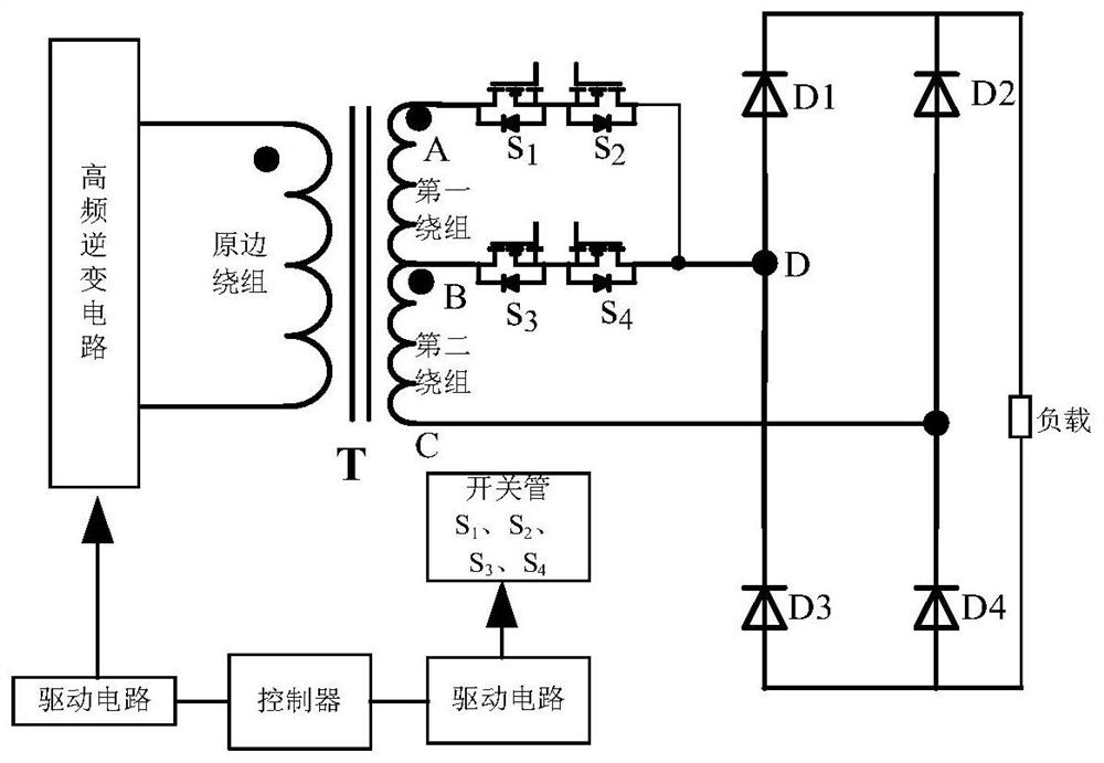
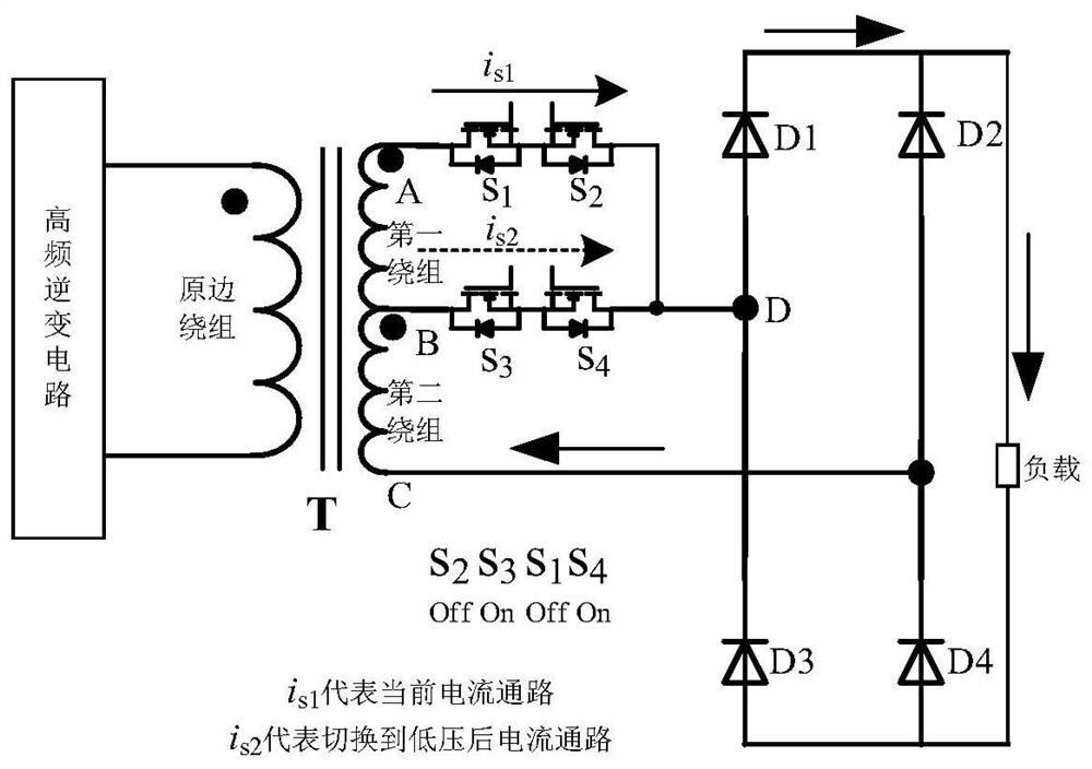
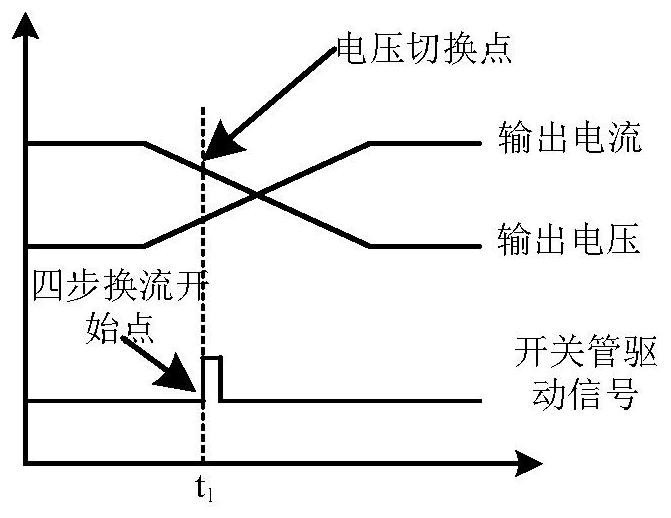
[0018] In a switching method applied to the switching device of the transformer winding of the charging module, the schematic diagram of the circuit topology of the switching device is as follows figure 1 shown. At present, the converter is in the output high voltage working state, the first winding and the second winding participate in the working process together, such as figure 2 As shown, assume the current path as i s1 As shown, the current flows from point A of the first winding to point D through switch tubes S1 and S2, and then returns to point C of the second winding through diode D1, load and D4. When the controller detects that the output voltage is lower than the voltage switching point, the controller adjusts the control value of the high-frequency inverter circuit according to the switching ratio of the windings, and starts the four-step commutation process, such as image 3 , Figure 4 As shown: first turn off the switch tube S2 at time t1, the body diode of...


PUM


Abstract

The invention discloses a switching method applied to a charging module transformer winding switching device. A high-frequency transformer, a switching tube, a controller, a driving circuit and a high-frequency inverter circuit are included. Three taps are arranged on the secondary side of the high-high frequency transformer, two taps are connected with switching tubes which are connected in series reversely, and the controller controls the high-frequency inverter circuit and the switching tubes through a driving circuit; and the controller adjusts the control quantity of the high-frequency inverter circuit according to the winding switching proportion, executes a four-step current conversion method at the same time, and controls the switch-on or switch-off of the switching tube, and the winding is switched from high voltage to low voltage or from low voltage to high voltage. According to the invention, flexible seamless switching between windings is realized, peak voltage is eliminated, and the service life of a switching tube is prolonged; the controller judges the directions of the secondary winding currents is1 and is2 according to the control quantity of the high-frequency inverter circuit, the current direction does not need to be judged through a detection circuit, and the circuit structure is simplified; the converter realizes continuous high-power output in different output stages, and the efficiency of the converter is improved.

Description

technical field [0001] The invention relates to the technical field of power electronics and control, in particular to a switching method applied to a transformer winding switching device of a charging module. Background technique [0002] With the development of the new energy vehicle industry, the voltage range of electric vehicle batteries is gradually expanding. High-power DC charging equipment must meet the charging needs of different types of electric vehicles and meet the wide voltage range output of 200V-1000V. Traditional transformers mostly adopt the secondary single-winding topology scheme, and the output voltage range is between 200V and 800V. It is difficult to meet the full power output in such a wide range in a single working mode. [0003] The existing method proposes to use a transformer secondary winding topology, which has been widely used. However, it uses a relay as a switching device, and the response speed of the relay is relatively slow. The winding m...

Claims


Application Information

Patent Timeline
Patent Type & Authority Applications(China)
IPC IPC(8): H02M3/335H02M7/48H02P13/06B60L53/22
CPCH02M3/33576H02M7/48H02P13/06B60L53/22H02M1/0038Y02T10/64Y02T10/70Y02T10/72Y02T10/7072Y02T90/14
Inventor 范建华徐鹏飞刘玉林李庆祥高文科张建李伟吴雪梅卢峰林志超程艳艳叶齐
Owner QINGDAO TOPSCOMM COMM
Why Eureka
Try Eureka