
High-speed permanent magnet synchronous motor composite rotor spiral winding preparation method

A permanent magnet synchronous motor and helical winding technology, applied in the manufacture of motor generators, stator/rotor bodies, inductors/transformers/magnets, etc., can solve the problems of continuous winding between layers, high-speed motor rotor stress concentration, time-consuming, etc.

Active Publication Date: 2020-10-27
BEIHANG UNIV +1
View PDF5 Cites 5 Cited by
  • Summary
  • Abstract
  • Description
  • Claims
  • Application Information

AI Technical Summary

Problems solved by technology

[0004] In order to solve the problems of eddy current loss and high-speed motor rotor stress concentration caused by harmonics in the rotor of high-speed permanent magnet synchronous motors, the present invention uses magnetic powder film and carbon fiber prepreg to form a composite magnetic material. Considering the special multi-layer structure of the high-speed permanent magnet synchronous motor, the present invention proposes a method for preparing a high-speed permanent magnet synchronous motor composite rotor spiral winding
During the spiral winding process, this method can ensure that the magnetic powder film of each layer is evenly distributed, especially can solve the problem of continuous winding between layers, and fundamentally solve the time-consuming problem of winding wrinkles at the end of the shaft or cutting and rewinding caused by continuous winding

Method used

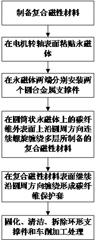
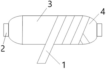
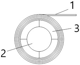

Image

  • High-speed permanent magnet synchronous motor composite rotor spiral winding preparation method
  • High-speed permanent magnet synchronous motor composite rotor spiral winding preparation method
  • High-speed permanent magnet synchronous motor composite rotor spiral winding preparation method

Examples


Embodiment Construction

[0029] The present invention will be further described below in conjunction with the accompanying drawings and examples. It should be understood that the following examples are intended to facilitate the understanding of the present invention, and have no limiting effect on it.

[0030] Such as figure 1 and 2 As shown, the helical winding preparation method of the high-speed permanent magnet synchronous motor composite rotor includes the following steps:

[0031] Step 1: preparing composite magnetic material 1;

[0032] 1) Mix carbon fiber with epoxy resin to prepare carbon fiber prepreg;

[0033] 2) Mix the magnetic powder with a series of additives such as epoxy resin binder, coupling agent, curing agent, plasticizer, etc. to prepare a magnetic powder film, and then heat the magnetic powder film at 80°C to make it in a molten state;

[0034] 3) In the composite material preparation equipment, the prepared carbon fiber prepreg is flattened to form a strip-shaped carbon fi...


PUM


Abstract

The invention belongs to the field of motor rotor manufacturing, and particularly relates to a high-speed permanent magnet synchronous motor composite rotor spiral winding preparation method which comprises the following steps: preparing a composite magnetic material; adhering the inner surface of the permanent magnet to the surface of the motor spindle; connecting and mounting circular truncatedcone metal supporting pieces at two ends of the permanent magnet; continuously and spirally winding multiple layers of prepared composite magnetic materials on the outer surface of the carbon fiber ofthe permanent magnet in the circumferential direction, and applying a pre-tightening force in the winding process; and after winding of the composite magnetic material is completed, continuously performing winding at the surface of the composite magnetic material to form a carbon fiber protective sleeve, then performing curing, cleaning, circular truncated cone metal supporting piece dismountingand turning treatment sequentially, and preparing the composite rotor. In the spiral winding process, it can be guaranteed that each layer of magnetic powder adhesive film is evenly distributed, particularly, the problem of interlayer continuous winding can be solved, and the problem that due to continuous winding, the end of the rotating shaft is wrinkled in a winding mode or time is wasted in the cutting and re-winding process is fundamentally solved.

Description

technical field [0001] The invention belongs to the field of motor rotor manufacturing, and in particular relates to a preparation method for spiral winding of a high-speed permanent magnet synchronous motor compound rotor. Background technique [0002] The helical winding technology of composite rotor of high speed permanent magnet synchronous motor is an important step in forming the rotor of high speed permanent magnet synchronous motor. [0003] Chinese application 201920489298.5 discloses a reinforced HDPE-PTFE composite winding pipe, in which the winding method is a spiral superposition winding method, which is mainly aimed at some strips suitable for lamination winding, and for some unsuitable lamination forms such as Composite magnetic materials, this method will cause inhomogeneity of the magnetic material. In addition, this method only solves the single-layer continuous winding, and does not solve the problem of multi-layer winding. Chinese application 2012800295...

Claims


Application Information

Patent Timeline
IPC IPC(8): H02K15/03H01F41/094H01F41/098H01F41/06B29C70/34
CPCB29C70/34H01F41/06H02K15/03H01F41/094H01F41/098
Inventor 王惠军张凤阁姚金宇
Owner BEIHANG UNIV
Learn More