Server, control key and magnetic induction triggering structure

A technology for controlling buttons and magnetic induction, which is applied in the server field, and can solve problems such as trigger insensitivity, fast wear of control switches, and rebound hysteresis

Inactive Publication Date: 2020-10-27
LANGCHAO ELECTRONIC INFORMATION IND CO LTD
View PDF16 Cites 0 Cited by
  • Summary
  • Abstract
  • Description
  • Claims
  • Application Information

AI Technical Summary

Problems solved by technology

However, in the long-term use process, due to the frequent contact and collision between the contact copper sheet and the control switch, and the excessive pressing force of the management personnel, the control switch wears out quickly and the service life is short, which is likely to cause damage. Normal trigger, trigger insensitivity phenomenon
In addition, the surface-to-surface friction between the contact copper sheet and the control switch also has the problems of trigger delay and rebound hysteresis caused by material sticking

Method used


Image

  • Server, control key and magnetic induction triggering structure
  • Server, control key and magnetic induction triggering structure

Examples


Embodiment Construction

[0026] The following will clearly and completely describe the technical solutions in the embodiments of the present invention with reference to the accompanying drawings in the embodiments of the present invention. Obviously, the described embodiments are only some, not all, embodiments of the present invention. Based on the embodiments of the present invention, all other embodiments obtained by persons of ordinary skill in the art without making creative efforts belong to the protection scope of the present invention.

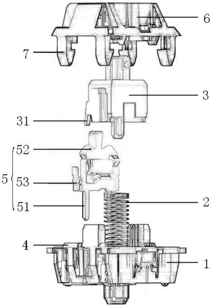
[0027] Please refer to figure 1 , figure 1 It is a schematic diagram of the overall structure of a specific embodiment provided by the present invention.

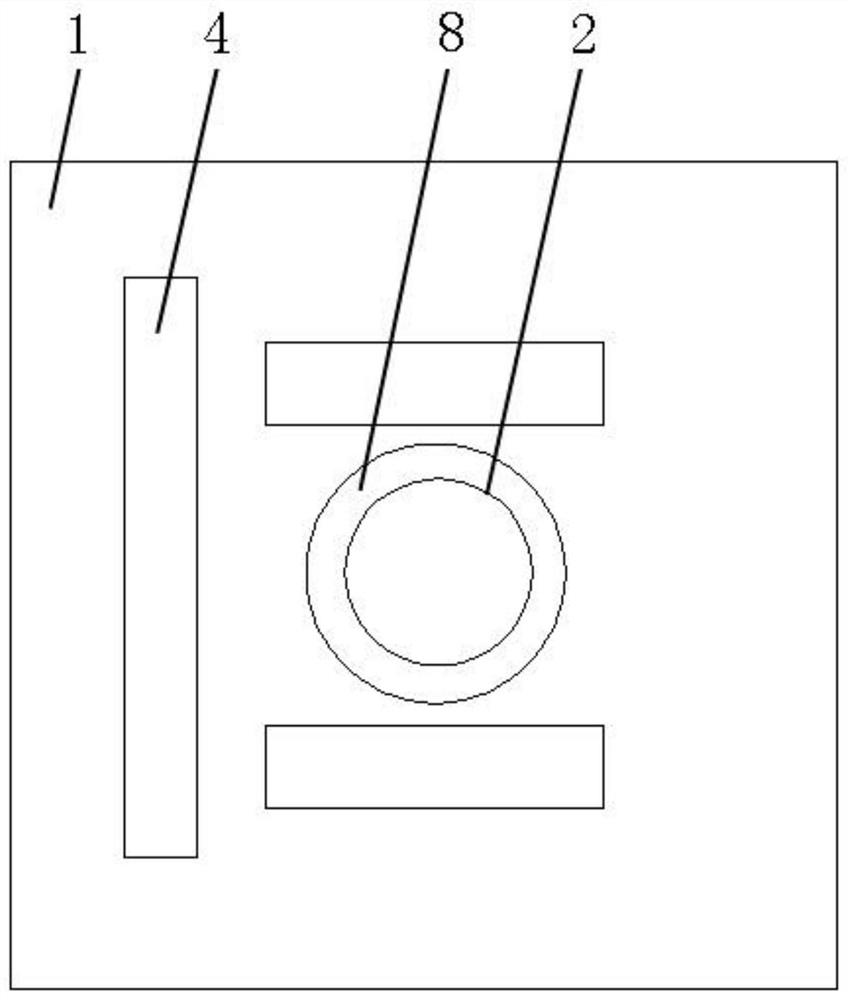
[0028] In a specific embodiment provided by the present invention, the magnetic induction trigger structure mainly includes a base 1 , a spring 2 , a shaft core 3 and a magnetic induction switch 4 .

[0029] Wherein, the base 1 is the main structure, which is mainly used for installing other components. ...


PUM


Abstract

The invention discloses a magnetic induction triggering structure. The structure comprises a base, a spring vertically arranged on the surface of the base, a shaft core arranged at the top end of thespring and used for moving in the vertical direction under the pressing effect, and a magnetic induction switch arranged on the surface of the base and used for triggering a preset output signal through the Hall effect when the shaft core is vertically pressed downwards to a preset distance. The invention provides a magnetic induction triggering structure. The Hall effect is utilized to trigger the key to output signals in the mode that the shaft core approaches the magnetic induction switch under the pressing effect. Key triggering control is achieved, the shaft core does not need to be in physical contact with the magnetic induction switch, so that the magnetic induction switch is prevented from being impacted and abraded, the service life can be prolonged, meanwhile, the shaft core andthe magnetic induction switch do not need to be in face-to-face friction abutting connection, the triggering delay and springback hysteresis phenomena can be reduced as much as possible, and the switch triggering sensitivity is improved. The invention also discloses a control key and a server, which have the above beneficial effects.

Description

technical field [0001] The invention relates to the technical field of servers, in particular to a magnetic induction trigger structure. The invention also relates to a control button and a server. Background technique [0002] With the development of electronic technology in China, more and more electronic devices have been widely used. [0003] A server is an important part of electronic equipment and a device that provides computing services. Since the server needs to respond to and process service requests, generally speaking, the server should have the ability to undertake and guarantee services. According to the different types of services provided by the server, it is divided into file server, database server, application server, WEB server, etc. [0004] In the era of big data, a large number of IT equipment will be centrally placed in the data center. These data centers contain various types of servers, storage, switches and a large number of cabinets and other ...

Claims


Application Information

Patent Timeline
Patent Type & Authority Applications(China)
IPC IPC(8): H01H13/10H01H13/14H01H13/20H01H13/32H01H13/02
CPCH01H13/14H01H13/20H01H13/10H01H13/32H01H13/02
Inventor 秦剑锋
Owner LANGCHAO ELECTRONIC INFORMATION IND CO LTD
Why Eureka
Try Eureka