
Method for installing and designing oil pipeline in alpine frozen soil area

An oil pipeline and design method technology, applied in pipeline laying and maintenance, pipeline support, computer-aided design, etc., can solve the problems of large stress changes, difficult control of the temperature field of the foundation soil, and the inability of pipeline laying technology and trenchless technology to meet the requirements. requirements, etc.

Pending Publication Date: 2020-10-27
BC P INC CHINA NAT PETROLEUM CORP +2
View PDF0 Cites 5 Cited by
  • Summary
  • Abstract
  • Description
  • Claims
  • Application Information

AI Technical Summary

Problems solved by technology

Therefore, the new pipeline installation design method of the system is put on the agenda. However, due to the difficulty in regulating the temperature field of the foundation soil in the permafrost area, the stress changes caused by the temperature difference between the inside and outside of the oil pipeline are large. It is necessary to fully consider the mechanical properties of the soil to prevent the permafrost layer destruction
[0005] In order to ensure the integrity and stability of the alpine permafrost and respond to the national environmental protection policy, the traditional pipeline laying technology and non-excavation technology cannot meet the requirements

Method used


Image

  • Method for installing and designing oil pipeline in alpine frozen soil area
  • Method for installing and designing oil pipeline in alpine frozen soil area
  • Method for installing and designing oil pipeline in alpine frozen soil area

Examples


Embodiment Construction

[0052] The following will clearly and completely describe the technical solutions in the embodiments of the present invention with reference to the accompanying drawings in the embodiments of the present invention. Obviously, the described embodiments are only some, not all, embodiments of the present invention. Based on the embodiments of the present invention, all other embodiments obtained by persons of ordinary skill in the art without creative efforts fall within the protection scope of the present invention.

[0053] It should be noted that if there is a directional indication (such as up, down, left, right, front, back...) in the embodiment of the present invention, the directional indication is only used to explain the position in a certain posture (as shown in the accompanying drawing). If the specific posture changes, the directional indication will also change accordingly.

[0054] In addition, in describing the present invention, the terms used are for the purpose ...


PUM


Abstract

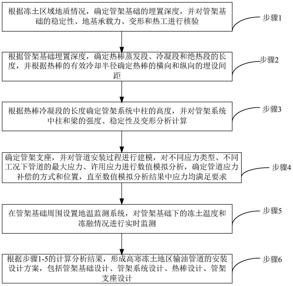
The invention discloses a method for installing and designing an oil pipeline in an alpine frozen soil area, which comprises the following steps of: determining the burying depth of a pipe frame foundation according to the geological condition of the frozen soil area, and checking the stability, the foundation bearing capacity, the deformation and the thermal engineering of the pipe frame foundation; determining the lengths of an evaporation section, a condensation section and a heat insulation section of the hot rod, and determining the burying distance of the hot rod according to the effective cooling radius of the hot rod; the height of a column of the pipe frame system is determined, and the strength, stability and deformation of the column and a beam in the pipe frame system are analyzed and calculated; determining a pipe frame support, modeling a pipeline installation process, performing numerical simulation analysis on the maximum stress and allowable stress of the pipeline under different stress types and different working conditions, and determining a mode and a position of pipeline stress compensation; a ground temperature monitoring system is arranged around the pipe frame foundation and used for monitoring the frozen soil temperature and the freezing and thawing conditions under the pipe frame foundation in real time; According to calculation and analysis results ofthe steps 1-5, an installation design scheme of the oil pipeline in the alpine frozen soil area is formed.

Description

technical field [0001] The invention relates to the technical field of oil and gas pipeline engineering, in particular to an installation and design method for an oil pipeline in an alpine permafrost region. Background technique [0002] The traditional laying technology of oil pipelines is the way of trench excavation and underground burial. At present, with the limitation of the geographical location of pipeline construction and the increasing complexity of terrain, pipeline trenchless technology has been widely used, including spanning technology and horizontal directional drilling technology. , pipe jacking tunnel technology, shield tunnel technology, mountain drilling and blasting tunnel technology, etc. [0003] Among them, in addition to spanning technology, pipelines using trenchless technology such as directional drilling still need to be laid underground and in mountains, which will inevitably have a certain impact on the geological and ecological environment of th...

Claims


Application Information

Patent Timeline
IPC IPC(8): G06F30/20F16L1/028F16L3/08F28D15/02G06F119/14G06F113/14
CPCG06F30/20F16L1/028F16L3/08F28D15/0275G06F2119/14G06F2113/14Y02T90/00
Inventor 左雷彬刘思萌李国辉徐大宝詹胜文黄泽民杨威
Owner BC P INC CHINA NAT PETROLEUM CORP
Learn More