
A release device for a pressure vessel

A pressure vessel and release device technology, applied in the field of pressure vessel devices, can solve the problems of high pressure, easy contamination, and poor operability of the pressure vessel, and achieve a solution with reduced fluid impact, strong controllability, and high safety. Effect

Active Publication Date: 2022-03-15
TIANXINFU (BEIJING) MEDICAL APPLIANCE CO LTD
View PDF13 Cites 0 Cited by
  • Summary
  • Abstract
  • Description
  • Claims
  • Application Information

AI Technical Summary

Problems solved by technology

However, this injection device has the following problems: 1. One end of the sleeve is open, and the protrusion for puncturing is also towards the open end, so the container opening is still exposed to the external environment for a long time after being punctured, It is easy to be polluted, and once an overflow occurs, the overflowed fluid is also easily polluted and cannot be used, resulting in unnecessary waste; 2. The pressure of the pressure vessel is relatively high, and the pressure vessel and the first sleeve are not fixed, directly There is a certain risk in puncturing the opening, for example, if you do not continue to press hard after puncturing, the pressure vessel and the first sleeve may collapse and separate; 3. In actual operation, the container cover of the pressure vessel is not particularly easy to be punctured. Therefore, when the device is in use, it needs to hold the first sleeve and the pressure vessel with both hands at least and press the pressure vessel hard to puncture, which is very laborious, and the piston used for puncturing is movable. It is easy to be pushed together along the pressing direction, making the pricking operation difficult and poor in operability

Method used


Image

  • A release device for a pressure vessel
  • A release device for a pressure vessel
  • A release device for a pressure vessel

Examples


Embodiment Construction

[0047] In order to explain the overall concept of the present application more clearly, the following will be described in detail by way of examples in combination with the accompanying drawings.

[0048] It should be noted that many specific details are set forth in the following description so as to fully understand the present application, but the present application can also be implemented in other ways different from those described here, therefore, the protection scope of the present application is not limited by the following limitations of the specific embodiments disclosed.

[0049] In addition, in the description of the present application, it should be understood that the terms "center", "upper", "lower", "front", "rear", "left", "right", "vertical", "horizontal" ", "Top", "Bottom", "Inner", "Outer", "Axial", "Radial", "Circumferential" and other indicated orientations or positional relationships are based on the orientations or positional relationships shown in the...


PUM


Abstract

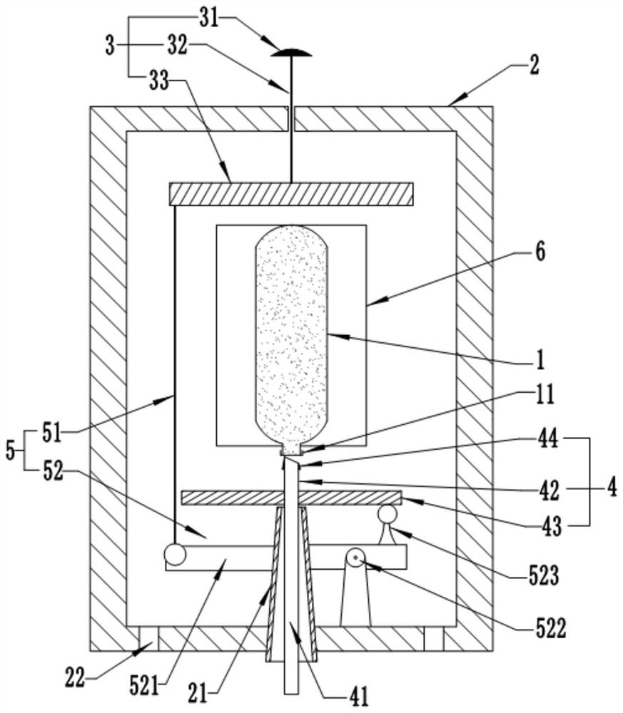
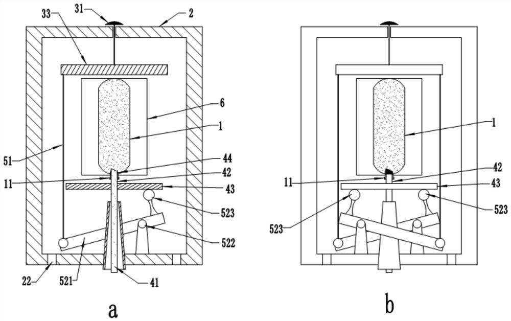
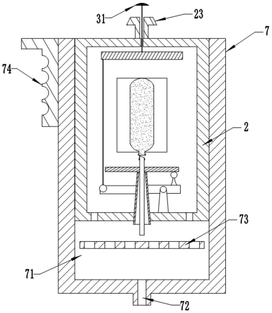
The present application provides a release device for a pressure vessel, comprising: an accommodation cylinder; a pushing part is provided at one end of the accommodation cylinder, one end of the pushing part is located outside the accommodation cylinder, and the other end is located in a cavity inside the accommodation cylinder; The other end of the housing cylinder is provided with a piercing part, and the piercing part has a through hole that communicates the inner cavity of the housing cylinder with the outside; the container opening of the pressure vessel faces the piercing part; the pushing part is connected to the piercing part through a linkage mechanism , and press the pushing part, the linkage mechanism pushes the piercing part to move in the opposite direction to the pressing direction, so as to pierce the container cover of the pressure vessel, and release the fluid in the pressure vessel to the outside of the accommodating cylinder through the through hole. The pressure vessel release device provided by this application has higher safety and can be operated with one hand when in use. The structural relationship design of the parts in the storage cylinder makes the opening of the pressure vessel less labor-saving and the controllability when releasing the fluid Strong, it can also help to reduce the fluid shock during release, making the bubbles in the discharged fluid smaller and more uniform.

Description

technical field [0001] The present application relates to the technical field of experimental devices, in particular to a device for releasing a pressure vessel that seals fluid at high pressure. Background technique [0002] Tissue engineering materials can be used to repair damaged parts of the human body, but in actual use, they often need to be trimmed or cut into the desired shape and size, which brings inconvenience to the operation and cannot maximize the use of repair materials. However, the tissue engineered material is made into a ready-to-use gel, which can be used according to actual needs, and the shape and size of the tissue engineered material can be determined by the operator, which is convenient to use and saves time. [0003] At present, there is a rapidly prototyping collagen gel that can be used as a tissue engineering material, but the collagen gel is sealed in a high-pressure small gas bottle in the form of fluid, and the high-pressure small gas bottle ...

Claims


Application Information

Patent Timeline
Patent Type & Authority Patents(China)
IPC IPC(8): F16K13/00F16J12/00F17C7/00F17C13/04
CPCF16K13/04F16J12/00F17C7/00F17C13/04F17C2221/031F17C2221/014F17C2223/0123F17C2205/032F17C2205/0323
Inventor 陈刚王国航栗国贝孙冰冰
Owner TIANXINFU (BEIJING) MEDICAL APPLIANCE CO LTD
Learn More