Profiling stripping structure applied to die opening engineering of U-shaped workpiece drawing die

A technology for drawing dies and workpieces, applied in the field of stamping and forming dies, can solve problems such as damage to skirts, and achieve the effect of improving the yield rate

Pending Publication Date: 2019-11-26
YIHE PRECISION IND SUZHOU
View PDF0 Cites 2 Cited by
  • Summary
  • Abstract
  • Description
  • Claims
  • Application Information

AI Technical Summary

Problems solved by technology

[0004] In view of this, the present invention provides a profiling stripping structure applied to the U-shaped workpiece drawing die opening project, which can effectively solve the problem of the skirt being damaged by the top block during the auxiliary stripping, thereby improving the yield of the product

Method used


Image

  • Profiling stripping structure applied to die opening engineering of U-shaped workpiece drawing die
  • Profiling stripping structure applied to die opening engineering of U-shaped workpiece drawing die
  • Profiling stripping structure applied to die opening engineering of U-shaped workpiece drawing die

Examples


Embodiment 1

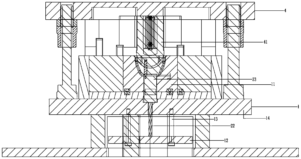
[0023] see Figure 1 to Figure 4 , the figure shows a profiling stripping structure applied to the U-shaped workpiece drawing die opening project provided by Embodiment 1 of the present invention. The U-shaped workpiece 3 has skirts 31 on both sides in the width direction. The shape stripping structure includes a profile stripping mechanism 2 installed on the lower die mechanism 1. The profile stripping mechanism 2 includes an upper top drive part 22 and a profile stripping block 23. The top top drive part 22 is a driving cylinder. The shape stripping block 23 is initially located in the preset space in the punch 11 of the lower die mechanism 1, and the driving shaft 225 of the top driving part 22 is connected to the profiling stripping block 23, and the driving shaft 225 is a V-shaped bending structure , the upper top driving part 22 drives the profiling stripping block 23 to go up and pushes the U-shaped workpiece 3 toward the direction of the punch 41 that is offset from th...

Embodiment 2

[0028] see Figure 1 to Figure 4 , the figure shows a profiling stripping structure applied to the U-shaped workpiece drawing die opening project provided by the second embodiment of the present invention. This embodiment further makes the following on the basis of the above embodiment As an improved technical solution: in the mold closing state, there is a gap of 3-4mm between the top surface of the profiling stripping block 23 and the punch 41, by setting the gap, the profiling stripping block can be Indent a section to prevent the punch from damaging the profiling stripping block.

Embodiment 3

[0030] see Figure 1 to Figure 4 , the figure shows a profiling stripping structure applied to the U-shaped workpiece drawing die opening project provided by the third embodiment of the present invention. This embodiment further makes the following on the basis of the above embodiments As an improved technical solution: an upper air intake chamber 222 and a lower air intake chamber 223 are arranged in the cylinder block 221 of the driving cylinder; 222 deflates, and the drive shaft 225 drives the profiling stripping block 23 to retract; when the mold is opened, the control valve controls the lower air intake cavity 223 to deflate, and at this time, the upper air intake cavity 222 intakes air, and the drive rod drives the profiling stripping block Block 23 protrudes and ejects U-shaped workpiece 3 . Through the setting of the above structure, when the drive shaft is retracted, the air intake in the lower air intake chamber can make the bottom of the entire cylinder more stable...


PUM

PropertyMeasurementUnit
Bend angleaaaaaaaaaa

Abstract

The invention provides a profiling stripping structure applied to die opening engineering of a U-shaped workpiece drawing die. According to the structure, skirt edges are arranged on the two sides ofthe width direction of a U-shaped workpiece, the profiling stripping structure comprises a profiling stripping mechanism arranged on a lower die mechanism, wherein the profiling stripping mechanism comprises an upward ejection driving part and a profiling stripping block, the profiling stripping block is located in a preset space in a male die of the lower die mechanism in an initial state, a driving shaft of the upward ejection driving part is connected with the profiling stripping block, the driving shaft is of a V-shaped bending structure, and the upward ejection driving part drives the profiling stripping block to move upwards and ejects the U-shaped workpiece in the direction deviated from a male die of an upper die mechanism during die opening. Compared with the prior art, the structure can be used for effectively solving the problem that an ejection block damages the skirt edges during auxiliary stripping, so that the product yield is improved.

Description

technical field [0001] The invention relates to the field of stamping dies, in particular to a profiling stripping structure applied to the mold opening project of a U-shaped workpiece drawing die. Background technique [0002] Such as figure 1 In the workpiece shape shown, the U-shaped workpiece 3 has skirts 31 on both sides in the width direction. In the mold opening process, it is mainly divided into three projects, namely the continuous mold, the drawing mold and the punching mold; among them, the main difficulty lies in the material stripping problem in the drawing mold opening state of the second project. The second process is stretching. When the mold is closed, the convex and concave molds are combined to form the product into the required style. When the mold is opened after molding, the product will have a state result: the first product is stuck in the concave module; the second product is stuck on the convex module, both of these states will affect the producti...

Claims


Application Information

Patent Timeline
IPC IPC(8): B21D45/04B21D22/20B21D37/10
CPCB21D22/20B21D37/10B21D45/04
Inventor 张海吕技伟耿朝阳王树吉
Owner YIHE PRECISION IND SUZHOU
Why Eureka
Try Eureka