Eureka AIR delivers breakthrough ideas for toughest innovation challenges, trusted by R&D personnel around the world.

Gas relay for realizing intelligent tripping of transformer and gas protection method

A relay and transformer technology, applied in the field of transformer protection devices, can solve the problems of prolonging the decision-making cycle and low intelligence level

Active Publication Date: 2020-10-23
国网山东省电力公司营销服务中心(计量中心) +2
View PDF10 Cites 4 Cited by
  • Summary
  • Abstract
  • Description
  • Claims
  • Application Information

AI Technical Summary

Problems solved by technology

The gas relay provided in the prior art document 1 can only provide the height information of the internal insulating oil level, and can only know the quantity of internal fault gas generated in the gas relay in real time, and cannot obtain the composition of internal fault gas and combustible gas for safe operation. Threat, extended decision cycle, low level of intelligence

Method used


Image

  • Gas relay for realizing intelligent tripping of transformer and gas protection method
  • Gas relay for realizing intelligent tripping of transformer and gas protection method
  • Gas relay for realizing intelligent tripping of transformer and gas protection method

Examples


Embodiment 1

[0066] Embodiment 1: A gas relay

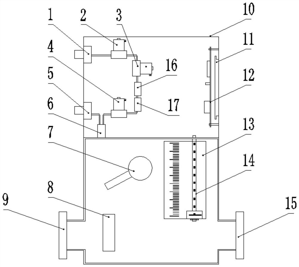
[0067] Such as figure 1 As shown, the present invention provides a gas relay, including: a main cavity and a measurement and control cavity, the main cavity is connected to the transformer body through the first flange interface 9, connected to the oil conservator through the second flange interface 15, and the measurement and control cavity A cavity is provided above the body cavity and is formed by a protective cover 10 for protecting components inside it.

[0068] The main chamber includes: a light gas level float switch 7, a float sensor 14 and a flow valve 8; the measurement and control chamber includes: a control module 12 and a combustible gas content detection module.

[0069] The light gas liquid level float switch 7 is respectively connected to the background system and the control module 12. If the gas volume of the gas relay reaches the light gas alarm threshold, the light gas liquid level float switch 7 sends a light gas alarm t...

Embodiment 2

[0080] Embodiment 2: a kind of gas protection method

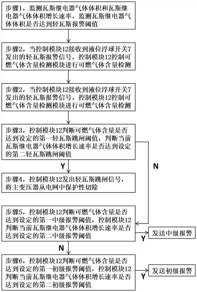
[0081] Such as figure 2 As shown, the present invention also provides a gas protection method based on the gas relay described in Embodiment 1, comprising the following steps:

[0082] Step 1, the control module 12 is connected to the float sensor 14 to monitor the gas volume of the gas relay and the growth rate of the gas volume of the gas relay; the control module 12 is connected to the liquid level float switch 7 to monitor whether the gas volume of the gas relay reaches the light gas alarm The threshold value makes the liquid level float switch 7 send out a light gas alarm signal.

[0083] Those skilled in the art can arbitrarily set the light gas alarm threshold according to the actual situation of the transformer site. In order to clearly illustrate this embodiment, preferably but not limitatively, the light gas alarm threshold is set to 250mL.

[0084] Specifically, monitoring the gas volume growth rate of the Bu...


PUM


Abstract

The invention discloses a gas relay for realizing intelligent tripping of a transformer and a gas protection method. The gas relay comprises a main body cavity and a measurement and control cavity, wherein two ends of the main body cavity are connected with a transformer body and an oil conservator; the measurement and control cavity is arranged above the main body cavity; the main body cavity internally comprises a light gas liquid level float switch, a float sensor and a flow valve; the measurement and control cavity internally comprises a control module and a combustible gas content detection module; the combustible gas content detection module is controlled by the control module to obtain a gas relay gas of the main control cavity, further conducts combustible gas content detection; and the control module is used for calculating a gas volume increase rate of the gas relay according to gas relay gas volume data of the floater sensor, judging an alarm level in combination with the combustible gas content, and sending an alarm signal of the corresponding level. According to the gas relay, the combustible gas content of the gas relay is measured, the single function mode of light gas alarm and heavy gas tripping in the prior art is broken through, and the working requirements of an existing extra-high voltage transformer can be met.

Description

technical field [0001] The invention belongs to the field of transformer protection devices, and more specifically relates to a gas relay and a gas protection method for realizing intelligent tripping of transformers. Background technique [0002] At present, the transformer non-electricity protection gas relay acts quickly and can quickly remove the internal fault of the transformer, but its function is relatively single, and it only relies on the principle of gas expansion and oil flow impact to realize the fault identification, especially after the light gas is activated, it only provides an alarm signal. Need Professionals can only determine whether there is a fault after sampling and testing the transformer oil, and then decide to take the next step based on the test results. The decision-making cycle is long. If the transformer fault worsens during this period, it will easily cause equipment damage and undermine the operation safety of the power grid. [0003] Prior ar...

Claims


Application Information

Patent Timeline
Patent Type & Authority Applications(China)
IPC IPC(8): H01F27/40H01H35/18H01H35/26G01N33/22G08B21/16
CPCG01N33/225G08B21/16H01F27/402H01F2027/404H01H35/18H01H35/26
Inventor 李云亭郭亮陈琳杨剑冯新岩杨硕刘涛张仲耀王毓琦郭腾炫张松辉张国栋聂兆明
Owner 国网山东省电力公司营销服务中心(计量中心)
Why Eureka
Eureka Blog
Learn More