
Mechanical continuously variable transmission

A continuously variable transmission, mechanical technology, applied in mechanical equipment, portable lifting devices, components with teeth, etc., can solve problems such as lack of driving pleasure, V-groove and transmission belt slippage, small transmission torque, etc.

Pending Publication Date: 2020-10-23
广州艾可米汽车科技股份有限公司
View PDF0 Cites 0 Cited by
  • Summary
  • Abstract
  • Description
  • Claims
  • Application Information

AI Technical Summary

Problems solved by technology

[0004] However, the shortcomings of traditional continuously variable transmissions are obvious: (1) V-shaped grooves and transmission belts are easy to slip. Due to the high precision of oil pressure control of CVTs, failures are prone to occur, resulting in insufficient pressing force, which makes V-shaped grooves and transmission belts slip, This is a common failure of continuously variable transmissions, and it is also the deadliest problem
(2) The transmission torque is small, limited by the maximum oil pressure of the continuously variable transmission system, generally the transmission torque is small
(3) Gear shift lag, because the CVT takes a long time to establish oil pressure, the pressing force between the V-shaped groove and the transmission belt cannot be increased in time, so the engine torque output will be limited during the acceleration of the car, preventing the engine torque from increasing Too fast to avoid slippage of the continuously variable transmission, the result is that the car has poor acceleration performance, is not suitable for intense driving, and lacks driving pleasure
(4) The hydraulic control system is complex, difficult to manufacture and high in cost

Method used


Image

  • Mechanical continuously variable transmission
  • Mechanical continuously variable transmission
  • Mechanical continuously variable transmission

Examples


Embodiment Construction

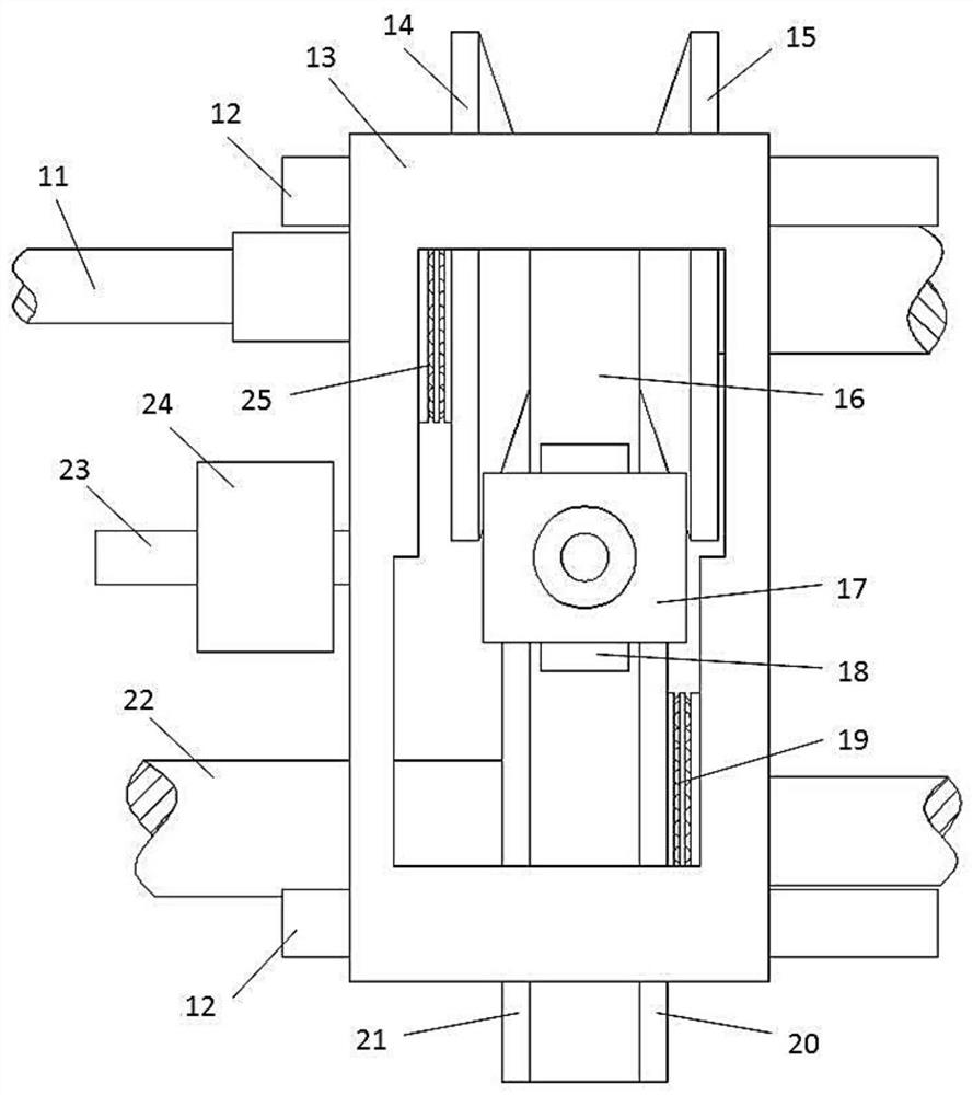
[0019] The present invention uses the tension wheel to provide the pressing force between the V-shaped groove of the continuously variable transmission and the transmission belt, adjusts the tensioning force of the transmission belt through the tension mechanism, and realizes the adjustment of the pressing force between the V-shaped groove and the transmission belt. The axial movement of the cage is controlled by a variable speed control mechanism to realize the change of the transmission ratio of the transmission.

[0020] Below, the technical solution of the present invention will be further described in conjunction with the drawings and specific embodiments of the description:

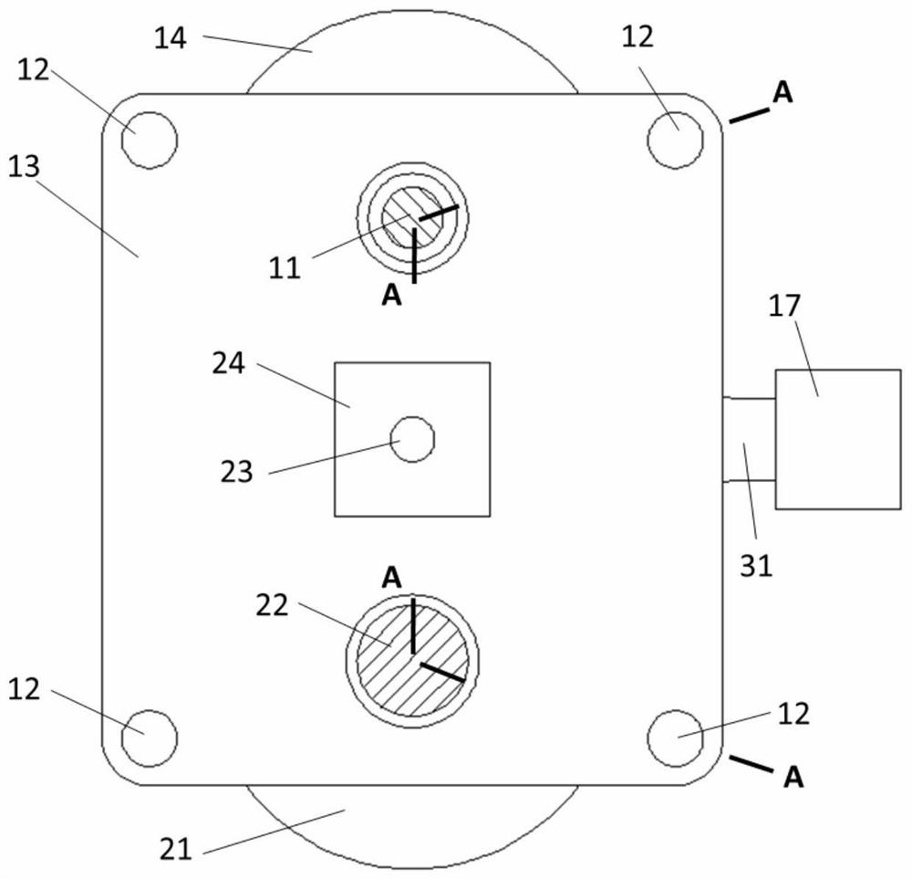
[0021] The mechanical continuously variable transmission consists of an input shaft 11, a guide rod 12, a cage 13, a driving disc 14, a driving fixed disc 15, a driven disc 20, a driven fixed disc 21, a transmission belt 16, a tensioning mechanism 17, a tensioning Wheel 18, variable speed control me...


PUM


Abstract

The invention discloses a mechanical continuously variable transmission. The mechanical continuously variable transmission comprises an input shaft, a driving fixed disc on the input shaft, an outputshaft, a driven fixed disc on the output shaft, a driving movable disc and a driven movable disc which move relative to the fixed discs, wherein a transmission belt is arranged on a V-shaped groove formed by the end faces of the fixed discs and the movable discs; and mechanical continuously variable transmission is characterized by further comprising a retainer and a tensioning device of the transmission belt, the driving fixed disc, the driving movable disc, the driven fixed disc and the driven movable disc are arranged in a retainer inner frame, the retainer is connected with the driving movable disc and the driven movable disc which are located on the left side and the right side of the retainer inner frame through thrust bearings, and the retainer is driven by a variable speed controlmechanism to move left and right in the axis direction of the driving fixed disc. According to the mechanical continuously variable transmission, the pressing force between the V-shaped groove and thetransmission belt is more reliable, so that slipping is avoided, meanwhile, larger pressing force can be adopted, larger torque can be transmitted, engine torque output does not need to be limited, the speed change response is fast, the acceleration performance of an automobile can be fully exerted, a complex oil pressure control system is omitted, the manufacturing difficulty and cost of the transmission are reduced, and the fuel efficiency of an automobile is improved.

Description

technical field [0001] The invention relates to the technical field of transmissions, in particular to a mechanical continuously variable transmission. Background technique [0002] Continuously variable transmission is a speed change device used in automobile transmission system. It has the characteristics of simple structure, small size, light weight, high transmission efficiency and low manufacturing cost. It is widely used in automobiles. [0003] The continuously variable transmission uses the friction force between the V-shaped groove and the transmission belt to realize power transmission. The currently used continuously variable transmission uses a hydraulic method to generate a pressing force between the V-shaped groove and the transmission belt, and at the same time adjusts the hydraulic oil to change the transmission ratio. . [0004] However, the shortcomings of traditional continuously variable transmissions are obvious: (1) V-shaped grooves and transmission be...

Claims


Application Information

Patent Timeline
IPC IPC(8): F16H9/16F16H55/56
CPCF16H9/16F16H55/56
Inventor 赵良红
Owner 广州艾可米汽车科技股份有限公司
Learn More