
Powder reinforced stirring friction riveting method and device

A technology of friction stirring and powder, which is applied in welding equipment, non-electric welding equipment, manufacturing tools, etc., and can solve problems affecting the metallurgical bonding strength of joints, keyhole defects, and poor air tightness

Active Publication Date: 2020-10-23
XI AN JIAOTONG UNIV
View PDF5 Cites 8 Cited by
  • Summary
  • Abstract
  • Description
  • Claims
  • Application Information

AI Technical Summary

Problems solved by technology

Riveting technology uses metal plastic deformation ability to achieve the purpose of connection by forming a mechanical lock between plates or between plates and rivets, but the connection strength of riveted joints is not high, the riveting forming force is large, the air tightness is poor, and the appearance quality is poor
The friction stir spot welding technology utilizes the friction stirring and extrusion effect between the stirring head and the metal material to form a metallurgical joint between the plasticized metal materials, but the traditional friction stir spot welding has keyhole defects
Although retraction friction stir spot welding can solve the keyhole problem, there are HOOK defects in retraction friction stir spot welding, which affect the metallurgical bonding strength of joints

Method used


Image

  • Powder reinforced stirring friction riveting method and device
  • Powder reinforced stirring friction riveting method and device
  • Powder reinforced stirring friction riveting method and device

Examples


Embodiment Construction

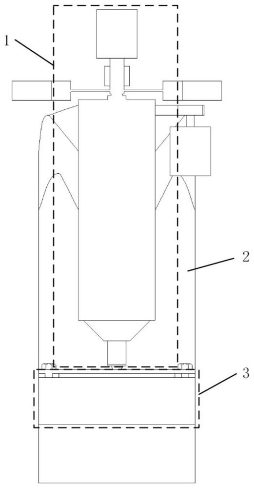
[0052] In order to make the purpose, technical solutions and advantages of the embodiments of the present invention clearer, the technical solutions in the embodiments of the present invention will be clearly and completely described below in conjunction with the accompanying drawings in the embodiments of the present invention. Obviously, the described embodiments It is some embodiments of the present invention, but not all of them. Based on the implementation manners in the present invention, all other implementation manners obtained by persons of ordinary skill in the art without creative efforts fall within the protection scope of the present invention. Accordingly, the following detailed description of the embodiments of the invention provided in the accompanying drawings is not intended to limit the scope of the claimed invention, but merely represents selected embodiments of the invention.

[0053] refer to figure 2 , image 3 and Figure 4 , a powder enhanced frict...


PUM


Abstract

The invention relates to a powder reinforced stirring friction riveting device. The powder reinforced stirring friction riveting device comprises a stirring friction riveting main shaft, a C-shaped rack and a workbench, wherein the stirring friction riveting main shaft comprises a rotary mechanism, a feeding mechanism, a vibrating / rotating mixing mechanism and a powder feeding mechanism; the stirring friction riveting main shaft is used for realizing the rotary motion and feed motion of a rivet and feeding and mixing powder; the C-shaped rack is used for fixing the stirring friction riveting main shaft and the workbench; and the workbench is mainly composed of a force cell, a sensor head, a tool die and a tool pressing plate and is used for clamping a to-be-riveted workpiece and testing the riveting acting force of the main shaft in real time. According to the powder reinforced stirring friction riveting device, the powder reinforced stirring friction riveting between same or differentlight plates at room temperature can be realized, a riveted stirring friction riveting joint without key hole defects and with good joint forming quality and high connecting strength can be obtained,the required riveting forming force is less than that of traditional riveting, and the powder reinforced stirring friction riveting device has the advantages of high efficiency, simplicity and convenience in operation and low energy consumption.

Description

technical field [0001] The invention belongs to the technical field of plate connection, and relates to a powder enhanced friction stir riveting welding method and device. Background technique [0002] With the continuous improvement of the comprehensive performance of mechanical equipment in the fields of aerospace, transportation, petrochemical and other fields, the continuous implementation of equipment lightweight and integration. The connection of lightweight plates of the same material, dissimilar materials, same thickness and different thickness has received extensive attention. At present, the technologies suitable for point connection of lightweight plates mainly include riveting and friction stir spot welding. Riveting technology uses metal plastic deformation ability to achieve the purpose of connection by forming a mechanical lock between plates or between plates and rivets, but the connection strength of riveted joints is not high, the riveting forming force is ...

Claims


Application Information

Patent Timeline
IPC IPC(8): B23K20/12B23P15/00
CPCB23K20/12B23P15/00B23K20/122B21J15/027B23K20/128B23K20/123B23K20/1255
Inventor 赵升吨张鹏王永飞李靖祥范淑琴
Owner XI AN JIAOTONG UNIV
Learn More