


Quick Research
Generate reliable direction feasibility study reports for your R&D in just a few steps.

Technical Q&A
Discover and master advanced knowledge NOW. Basics, ideas, possibilities, all at once.

Find Solutions
As an expert in R&D theories, this can generate solutions to your technical problems instantly.

Evaluate Feasibility
Analyze your overall solution with one click, know your potential R&D risks in advance.

Monitor Landscape
Get weekly tech updates, stay abreast of the latest tech innovations and key insights.
Surface paint vehicle spraying device for inverter production
A technology of spraying device and inverter, which is applied in the direction of spraying device, etc., can solve problems such as difficult inverter cycle rotation spraying, low inverter spraying efficiency, and inconvenient handling
- Summary
- Abstract
- Description
- Claims
- Application Information
AI Technical Summary
Problems solved by technology
Method used
Image

Examples
Embodiment 1
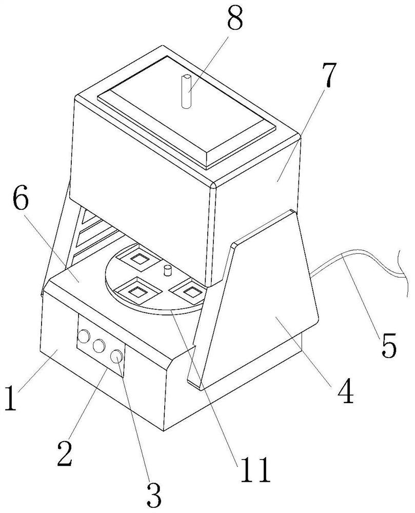
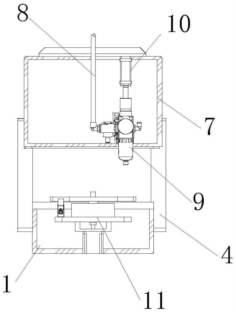
[0034] see figure 1 and figure 2 , the present invention provides a surface paint spraying device for inverter production through improvement, including a base plate 1, an operating table 6, a fixed frame 7, a first cylinder 10 and a circulation feeding mechanism 11, and the front end of the base plate 1 is provided with Control panel 2, button 3 is installed on the front end of control panel 2, side panels 4 are fixed on the left and right sides of base plate 1, power wires 5 are fixed on the rear end of base plate 1, circulation feeding mechanism 11 is installed and fixed inside base plate 1, and the top of base plate 1 is set There is an operation table 6, a fixed frame 7 is arranged on the top of the side plate 4, and a delivery pipe 8 is embedded in the top of the fixed frame 7, and the delivery pipe 8 communicates with the upper left end of the nozzle 9, and the nozzle 9 is fixedly connected with the lower end of the first cylinder 10, and the second A cylinder 10 is l...
Embodiment 2
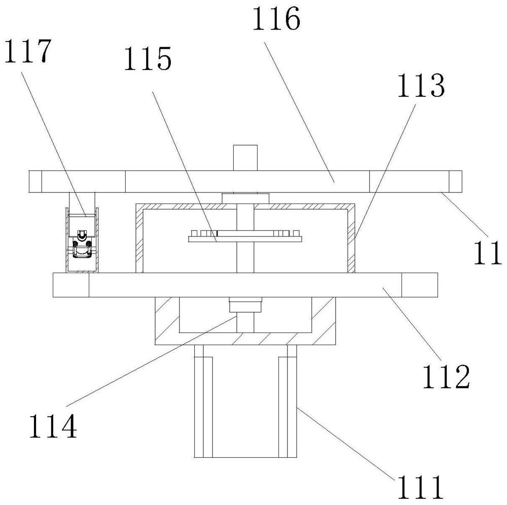
[0040] The present invention provides a surface paint spraying device for inverter production through improvement. The protective frame 113 is in the shape of a cuboid with an internal cavity, which is beneficial to install and fix the gap rotation mechanism 115. The surface of the pulley 1176 It is smooth, and the pulley 1176 is embedded in the inner side of the fixing piece 1177, which is beneficial to guide the top plate 1174.
[0041] The present invention provides a surface paint spraying device for inverter production through improvement, and its working principle is as follows;
[0042] First, before use, the surface paint spraying device used for inverter production is placed horizontally, so that the base plate 1 is fixed and supported on the device, and then connected to the delivery pipe 8 through an external spraying pipe, and the first One cylinder 10 and the second cylinder 1173 are connected with external pneumatic equipment;
[0043] Second, when in use, conne...
PUM
 Abstract
Description
Claims
Application Information
 - R&D Engineer
- R&D Manager
- IP Professional
- Industry Leading Data Capabilities
- Powerful AI technology
- Patent DNA Extraction
Browse by: Latest US Patents, China's latest patents, Technical Efficacy Thesaurus, Application Domain, Technology Topic, Popular Technical Reports.
© 2024 PatSnap. All rights reserved.Legal|Privacy policy|Modern Slavery Act Transparency Statement|Sitemap|About US| Contact US: help@patsnap.com