
Method and device for testing implantable biological monitoring sensors

A bio-monitoring and testing device technology, applied in sensors, blood characterization devices, diagnostic recording/measurement, etc., can solve problems such as low detection efficiency and inability to fully simulate the detection accuracy of actual human body temperature

Active Publication Date: 2020-10-23
ZHEJIANG POCTECH
View PDF5 Cites 0 Cited by
  • Summary
  • Abstract
  • Description
  • Claims
  • Application Information

AI Technical Summary

Problems solved by technology

[0002] Implantable biomonitoring sensors are used to implant on the surface of human skin and monitor human blood glucose parameters in real time. In order to ensure that the sensor can maintain good contact with human subcutaneous tissue fluid after entering the human body during implantation, it is necessary to enter the market when implantable biomonitoring sensors enter the market. Before performing performance monitoring, the current test of implantable biomonitoring sensors is generally carried out by electrochemical workstation. When testing the sensor on the electrochemical workstation, the specific solution is to configure the simulated human tissue fluid, and then install the sensor on the workstation. , so that the implanted part of the sensor is soaked in the solution, and the data is analyzed during the test process, but limited by the workstation mode, only a single sensor after cutting can be installed each time, the detection efficiency is low and the actual human body cannot be completely simulated. The temperature makes the detection accuracy poor

Method used


Image

  • Method and device for testing implantable biological monitoring sensors
  • Method and device for testing implantable biological monitoring sensors
  • Method and device for testing implantable biological monitoring sensors

Examples


specific Embodiment 1

[0047] The method for testing the activity of an implantable biological monitoring sensor of the present invention has the following steps:

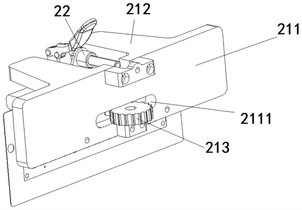
[0048] S1: Prepare a joint assembly unit frame 9. The joint assembly unit frame 9 includes a flexible substrate and a glass frame surrounding the outside of the flexible substrate. The flexible substrate is provided with implantable biological monitoring sensor units in parallel, so The implantable bio-monitoring sensor unit includes an electrode part and an implant part 14 formed at the lower end of the electrode part, the electrode part is connected to the flexible substrate, and the rest part is separated from the flexible substrate;

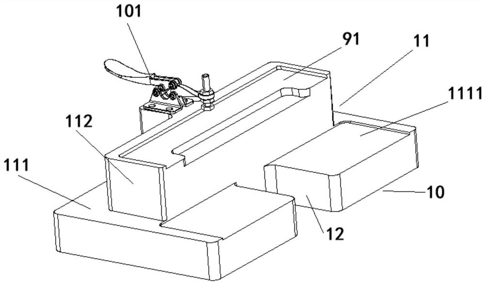
[0049] S2: Fix the clamping, clamp the coupling unit frame 9 to the sensor coupling clamp 2 through the auxiliary tooling 10, turn the coupling unit frame 9 to completely expose the implantation part 14 of the biological monitoring sensor, and then rotate the sensor coupling clamp 2 The upper buckle plate 21...

specific Embodiment 2

[0057] The anti-interference test method of an implanted biological monitoring sensor of the present invention, the test method steps are as follows:

[0058] S1: Prepare a joint assembly unit frame 9. The joint assembly unit frame 9 includes a flexible substrate and a glass frame surrounding the outside of the flexible substrate. The flexible substrate is provided with implantable biological monitoring sensor units in parallel, so The implantable bio-monitoring sensor unit includes an electrode part and an implant part 14 formed at the lower end of the electrode part, the electrode part is connected to the flexible substrate, and the rest part is separated from the flexible substrate;

[0059] S2: Fix the clamping, clamp the coupling unit frame 9 to the sensor coupling clamp 2 through the auxiliary tooling 10, turn the coupling unit frame 9 to completely expose the implantation part 14 of the biological monitoring sensor, and then rotate the sensor coupling clamp 2 The upper buckl...

specific Embodiment 3

[0064] The reference potential test method of an implantable biological monitoring sensor of the present invention, the test method steps are as follows:

[0065] S1: Prepare a joint assembly unit frame 9. The joint assembly unit frame 9 includes a flexible substrate and a glass frame surrounding the outer side of the flexible substrate. The flexible substrate is provided with implantable biological monitoring sensor units in parallel, so The implantable bio-monitoring sensor unit includes an electrode part and an implant part 14 formed at the lower end of the electrode part, the electrode part is connected to the flexible substrate, and the remaining part is separated from the flexible substrate;

[0066] S2: Fix the clamping, clamp the coupling unit frame 9 to the sensor coupling clamp 2 through the auxiliary tooling 10, turn the coupling unit frame 9 to completely expose the implantation part 14 of the biological monitoring sensor, and then rotate the sensor coupling clamp 2 The...


PUM


Abstract

The invention discloses a method and device for testing implantable biological monitoring sensors. The device comprises a testing device and a sensor coupling clamp which can be clamped on the testingdevice, the test device comprises a support, a test bench fixed on the support, and an auxiliary tool used for assisting the sensor coupling clamp in clamping a coupling unit frame, and the auxiliarytool comprises a clamping clamp and an auxiliary quick clamp fixedly installed on the clamping clamp. Compared with traditional testing devices, the sensors in the coupling unit frame need to be cutin advance, and the sensors are cut into separate sensors and need to be clamped and tested one by one. According to the invention, the whole row of sensors can be detected on the premise that the sensors do not need to be singly cut, clamped and fixed for detection, and compared with the traditional detection devices, the detection efficiency of the device provided by the invention is higher.

Description

Technical field [0001] The invention relates to the technical field of equipment detection, in particular to a testing method and a device for an implanted biological monitoring sensor. Background technique [0002] Implantable bio-monitoring sensors are used to implant the human skin surface and monitor human blood glucose parameters in real time. In order to ensure that the sensor can maintain good contact with the human subcutaneous tissue fluid after entering the human body during implantation, the implantable bio-monitoring sensor needs to enter the market Before performing performance monitoring, the current test of implantable bio-monitoring sensors is generally carried out by electrochemical workstations. When the sensors are tested on the electrochemical workstations, the solution is configured to simulate human tissue fluid, and then the sensors are installed on the workstation , So that the implanted part of the sensor is immersed in the solution, and the data is analy...

Claims


Application Information

Patent Timeline
IPC IPC(8): A61B5/1495A61B5/00A61B5/145G01N27/26
CPCA61B5/1495A61B5/6847A61B5/14503G01N27/26
Inventor 陈争张亚南
Owner ZHEJIANG POCTECH
Learn More