Optical device

A technology for optical equipment and optical fibers, which is applied in the field of optical equipment with reinforced structures, and can solve problems such as damage to the mechanical reliability of optical fiber OF

Inactive Publication Date: 2020-10-20
THE FUJIKURA CABLE WORKS LTD
View PDF8 Cites 0 Cited by
  • Summary
  • Abstract
  • Description
  • Claims
  • Application Information

AI Technical Summary

Problems solved by technology

As a result, the mechanical reliability

Method used


Image

  • Optical device
  • Optical device
  • Optical device

Examples


Embodiment Construction

[0017] 〔Structure of optical equipment〕

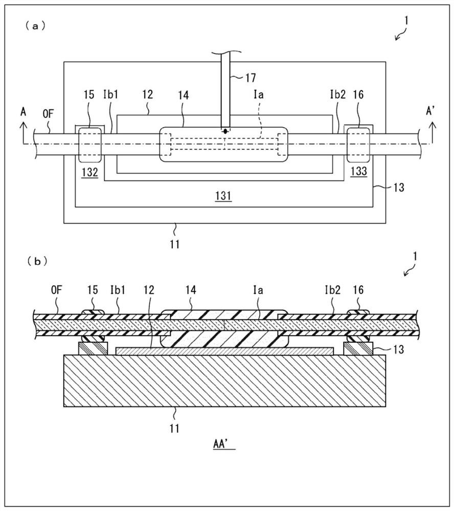
[0018] refer to figure 1 The structure of the optical device 1 according to one embodiment of the present invention will be described. exist figure 1 (a) is a top view of the optical device 1, figure 1 (b) is a sectional view of the optical device 1 . also, figure 1 The sectional view shown in (b) is figure 1 The arrow view of the AA' section shown in (a).

[0019] Such as figure 1 As shown, the optical device 1 includes an optical fiber OF, a heat sink 11 , a heat conductor 12 , a support 13 , a resin body 14 , an adhesive 15 , and an adhesive 16 . In addition, although the heat conductor 12 and the support body 13 are members provided on the upper surface of the heat sink 11, they are mutually independent members.

[0020] The optical fiber OF is an optical fiber in which two optical fibers are fused, and includes a fusion point. The vicinity of the melting point of the optical fiber OF constitutes the coating removal ...


PUM


Abstract

The present invention implements an optical device capable of suppressing an increase in the temperature of an optical fiber while ensuring mechanical reliability. An optical device (1) includes a thermal conductor (12), a support (13), and an optical fiber (OF). The support (13) is separated from the thermal conductor (12) and has a smaller thermal expansion rate than the thermal conductor (12).The optical fiber (OF) is brought into thermal contact with the thermal conductor (12) via a resin body (14) covering a stripped section (Ia), and is secured to the support (13) in each of two coatingsections (Ib1, Ib2).

Description

technical field [0001] The present invention relates to an optical device including an optical fiber provided with a coating-removed section, and a reinforcing structure for reinforcing the coating-removed section. Background technique [0002] A coating removal section is often provided in an optical fiber. The coating removal section refers to a section of the optical fiber in which the resin coating is removed and the glass cladding is exposed. For example, when two optical fibers are fused, a coating removal section is provided near the fusion point. In addition, a coating removal section is also provided in a cladding mode separator for removing cladding mode light from an optical fiber. [0003] The coating-removed section is inferior in mechanical strength compared to other sections. Therefore, various reinforcement structures for reinforcing the coating removal section have been employed. As documents disclosing the reinforcement structure of the coating removal ...

Claims


Application Information

Patent Timeline
IPC IPC(8): G02B6/255
CPCG02B6/2558
Inventor 内山圭祐柏木正浩岛研介
Owner THE FUJIKURA CABLE WORKS LTD
Why Eureka
Try Eureka