
System for calculating the minimum torque at the wheel of a motor vehicle and system for determining the moment at which the foot is lifted from the accelerator using such a calculation system

A computer, the smallest technology, applied in the direction of road vehicle drive control system, vehicle components, vehicle subunit functions, etc.

Pending Publication Date: 2020-10-20
RENAULT SA
View PDF8 Cites 0 Cited by
  • Summary
  • Abstract
  • Description
  • Claims
  • Application Information

AI Technical Summary

Problems solved by technology

[0002] There is an issue with providing vehicle deceleration when the foot is lifted in order to reach a target location and target speed based on the current state of the vehicle and based on information about the trip originating from the navigation system

Method used


Image

  • System for calculating the minimum torque at the wheel of a motor vehicle and system for determining the moment at which the foot is lifted from the accelerator using such a calculation system
  • System for calculating the minimum torque at the wheel of a motor vehicle and system for determining the moment at which the foot is lifted from the accelerator using such a calculation system

Examples


Embodiment Construction

[0032] During normal use of a vehicle, it is common to observe phases of deceleration of the vehicle without the brakes applied ("coasting"). The driver attempts to decelerate to reach the target speed in a more flexible manner than by using the brakes, and more often than not, at a given moment in the journey, i.e., when the vehicle reaches a given journey event (curve, climb, roundabout, Toll booths, etc.) to obtain this target speed. To do this, the driver lifts his or her foot off the accelerator pedal. This can lead to two situations.

[0033] In the first case, the lift of the foot results in a reduction in fuel supply to the drive train in order to reduce consumption (and CO 2 generated) and generate engine braking.

[0034] In the second case, the lift of the foot results in entering a free-riding mode (or "sailing" mode), also known as idle / stop, which is intended to make the vehicle more stable, make the most of the vehicle's inertia, and avoid the driver Acceler...


PUM


Abstract

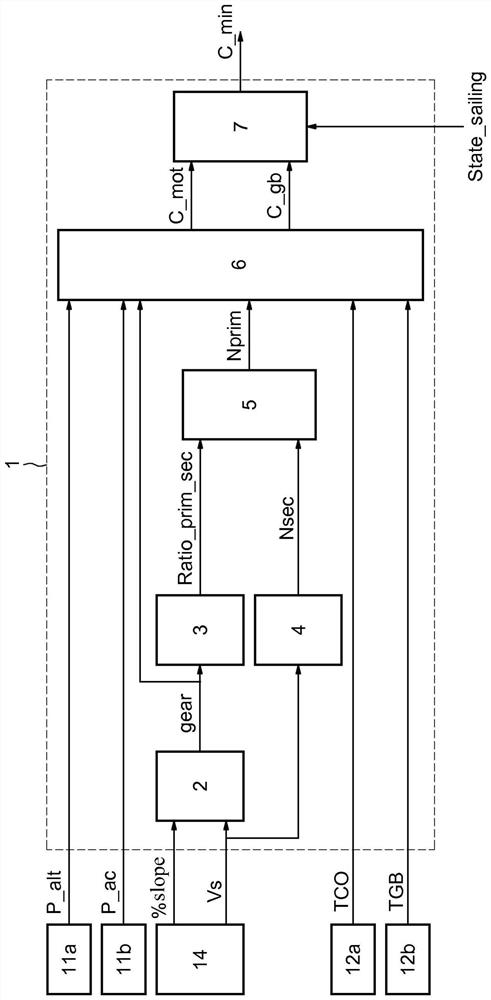
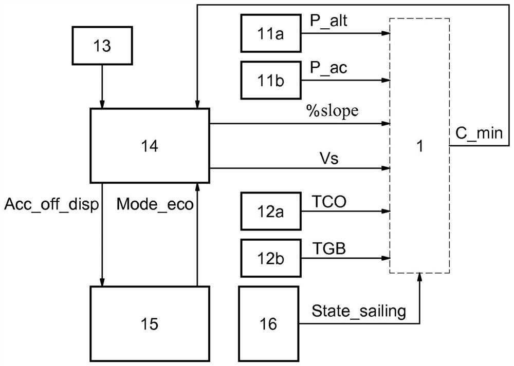
The invention relates to a system for calculating the minimum torque at the wheel of a motor vehicle provided with at least one temperature sensor of the engine (12a) and of the transmission fluid (12b), at least one power sensor of the alternator (11a) and at least one the air-conditioning system (11b), and at least one driving assistance computer (14). A calculation system comprising: a determining means (2) for determining the gear engaged as a function of the slope on which the vehicle is driving and the speed of the vehicle coming from the driving assistance computer (14); a means for determining (3) a ratio between the speed of rotation of the input shaft and the speed of rotation of the output shaft of the drive train as a function of the gear engaged; a calculation means (4) for calculating a speed of rotation of the output shaft as a function of the speed of the vehicle; a calculation means (5) for calculating the speed of rotation of the input shaft as a function of the ratioand the speed of rotation of the output shaft; a calculation means (6) for calculating the resisting torque of the engine and the drag of the gearbox as a function of the power of the alternator, thepower of the air-conditioning air compressor, the engine temperature, the temperature of the transmission fluid, the gear engaged and the speed of rotation of the input shaft; and a calculation means(7) for calculating the minimum torque as a function of the resisting torque of the engine, the drag of the gearbox and the state of the sailing mode.

Description

technical field [0001] The technical field of the invention is controlling the power train of a motor vehicle, and more particularly controlling torque at the wheels of such a vehicle. Background technique [0002] There is a problem with providing vehicle deceleration when the foot is lifted in order to reach a target position and target speed based on the current state of the vehicle and based on information about the trip originating from the navigation system. [0003] To solve this problem, there is a need to predictively determine the minimum torque at the wheels due to the power train in a motor vehicle when the foot is lifted off the accelerator pedal. [0004] From the prior art, document US 8855844 B2 and document US 8606459 B2 are known. However, these documents cannot solve this technical problem. Contents of the invention [0005] The subject of the invention is a system for calculating the minimum torque at the wheels of a motor vehicle equipped with at lea...

Claims


Application Information

Patent Timeline
IPC IPC(8): B60W30/18B60W40/12B60W50/00B60W50/14B60W40/10B60W40/107
CPCB60W40/12B60W50/0097B60W50/14B60W30/18072B60W40/1005B60W2030/18081B60W2030/1809B60W2050/0041B60W2510/0208B60W2510/0638B60W2510/0676B60W2510/1005B60W2510/1015B60W2510/104B60W2510/107B60W2510/305B60W2520/10B60W2540/10B60W2540/215B60W2556/50B60W2552/15B60W2530/16Y02T10/60B60K35/00B60Y2300/18066B60Y2400/30B60K35/10B60K35/22
Inventor R·迪亚斯-潘扎
Owner RENAULT SA
Learn More