Medical garbage can

A technology of trash cans and barrels, applied in trash cans, garbage collection, household appliances, etc., can solve problems such as increasing the infection risk of medical staff

Inactive Publication Date: 2020-10-20
THE FIRST AFFILIATED HOSPITAL OF ARMY MEDICAL UNIV
View PDF5 Cites 2 Cited by
  • Summary
  • Abstract
  • Description
  • Claims
  • Application Information

AI Technical Summary

Problems solved by technology

[0003] The present invention intends to provide a medical trash can to solve the problem of increasing the infection risk of medical staff when the common trash can is used

Method used


Image

  • Medical garbage can
  • Medical garbage can
  • Medical garbage can

Examples


Embodiment 1

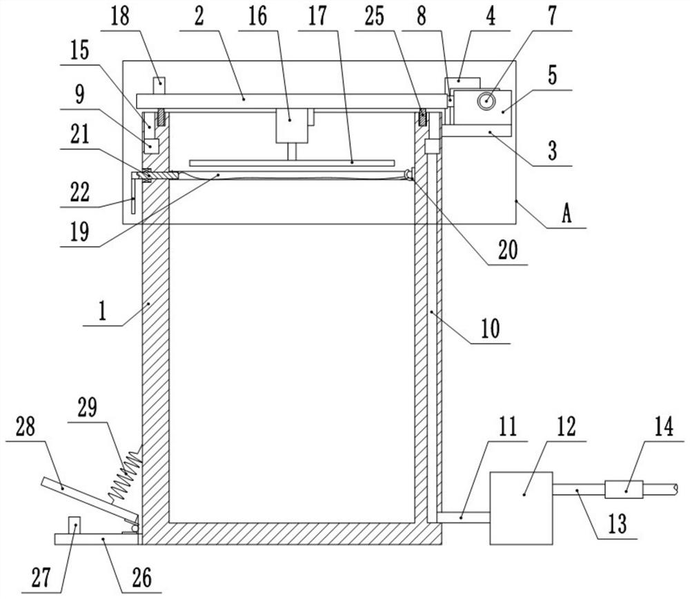
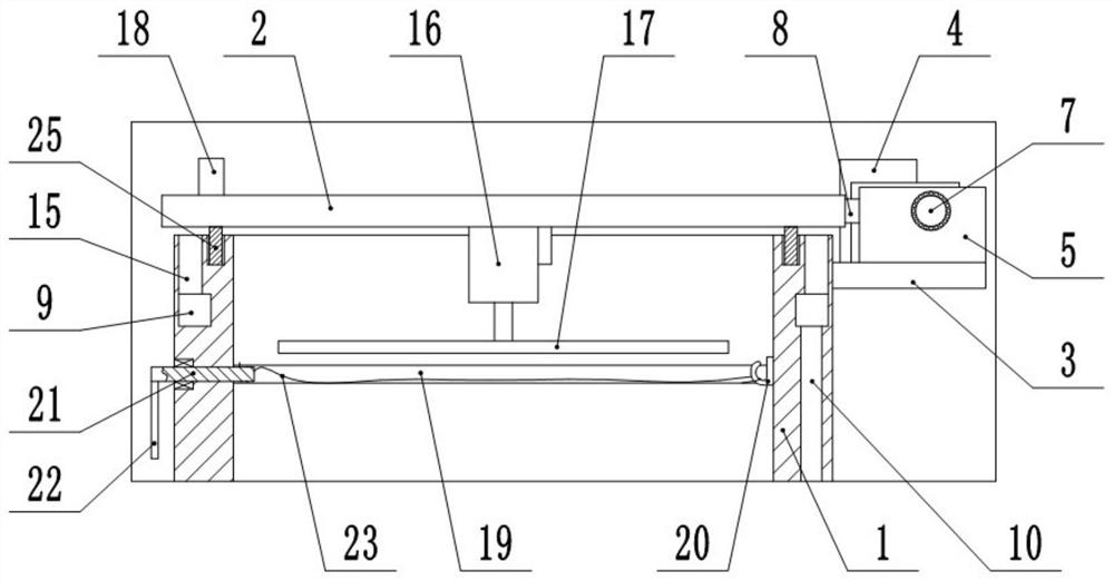
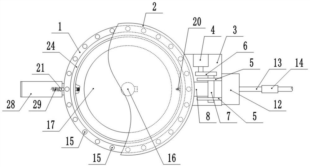
[0033] This embodiment is basically as figure 1 and figure 2 Shown: a kind of medical waste bin, comprises bucket body 1 and bucket lid 2, and the top of bucket body 1 is fixedly installed with the mounting plate 3 that horizontally arranges, and combines image 3 As shown, the mounting plate 3 is fixedly installed with a drive motor 4 and two opposite vertical plates 5, the output end of the drive motor 4 is connected to a rotating shaft 7 through a reducer 6, and the rotating shaft 7 is connected in rotation with the vertical plate 5 through a bearing; The right end of 2 is welded with connecting plate 8, and the right end of connecting plate 8 is welded with rotating shaft 7. In this embodiment, the drive motor 4 is a forward and reverse motor, and the drive motor 4 rotates clockwise for a period of time (about 7s), then stops for a period of time (about 10s), and then rotates counterclockwise for a period of time (about 7s), thereby leaving Go out sufficient time so tha...

Embodiment 2

[0046] The difference between this embodiment and Embodiment 1 is that: Figure 4 As shown, the right end of the rotating roller 21 is provided with an annular groove 30 , and the two free ends of the twisted rope 23 are all knotted in the annular groove 30 of the rotating roller 21 . In this embodiment, the annular groove 30 is used to limit the twisted rope 23 after knotting, so as to prevent the twisted rope 23 from detaching from the rotating roller 21 during the twisting process, thereby ensuring that the twisted rope 23 can successfully seal the garbage bag.

Embodiment 3

[0048] The difference between this embodiment and embodiment one or two is; Figure 5 As shown, the filter 14 is not installed in the exhaust pipe 13, but the exhaust pipe 13 is connected with a liquid storage chamber 31, and a sponge strip 32 is placed in the liquid storage chamber 31, and the sponge strip 32 extends into the exhaust pipe 13 And the sponge strip 32 is filled with the exhaust pipe 13, and the liquid storage cavity 31 is filled with 75% alcohol solution. The top of the liquid storage chamber 31 is communicated with a liquid replenishment tube 33 , and the end of the liquid replenishment tube 33 is screwed with a screw cap 34 .

[0049] In this embodiment, a section of the exhaust pipe 13 is filled with a sponge strip 32, and after the sponge strip 32 absorbs the 75% alcohol solution in the liquid storage chamber 31, when the air in the exhaust pipe 13 passes through the sponge strip 32, 75% The alcohol solution kills viruses in the air, so the sanitized air ca...


PUM


Abstract

The invention relates to the field of medical equipment, and discloses a medical garbage can. The medical garbage can comprises a can body and a can cover, a mounting plate is fixedly mounted at the top of the can body, a driving motor is fixedly mounted on the mounting plate, the output end of the driving motor is connected with a rotating shaft through a speed reducer, and the rotating shaft isfixedly connected with the end of the can cover; an annular cavity and a vertical channel are formed in the circumferential wall of the can body, the top end of the channel communicates with the annular cavity, the bottom end of the channel communicates with an air suction pipe, the end, away from the can body, of the air suction pipe communicates with an exhaust fan, the exhaust fan communicateswith an exhaust pipe, a plurality of vertical air suction holes are formed in the top of the circumferential wall of the can body, and the bottom ends of the air suction holes communicate with the annular cavity. According to the medical garbage can disclosed by the invention, the exhaust fan is used for extracting air in the channel and the annular cavity, so that the air suction holes suck the air above the can body, the air flow direction can be controlled in the opening and closing process of the can cover, free flowing of air flow carrying the virus is avoided, the possibility that medical staff make contact with the virus is reduced, and the infection risk is further reduced.

Description

technical field [0001] The invention relates to the field of medical equipment, in particular to a medical trash can. Background technique [0002] At present, the trash cans used in hospitals are ordinary trash cans with lids. During the COVID-19 epidemic, medical staff need to wear protective clothing to protect themselves and reduce the risk of infection. However, because the protective clothing is relatively fluffy, when the medical staff throws the discarded protective clothing into the trash can, in order to prevent the protective clothing from occupying a large space and reduce the utilization rate of the trash can, the medical staff usually use sticks or other tools Gently compress medical waste such as protective clothing, so that the trash can can hold more medical waste. However, in the above process, when opening or closing the lid of the trash can, and compressing medical waste such as protective clothing, airflow will be generated, and the flow direction of th...

Claims


Application Information

Patent Timeline
IPC IPC(8): B65F1/14B65F1/06B65F1/16
CPCB65F1/14B65F1/06B65F1/16
Inventor 谭琼阎萍李红雨孔维林周莲蒋婷
Owner THE FIRST AFFILIATED HOSPITAL OF ARMY MEDICAL UNIV
Why Eureka
Try Eureka