
Garbage treatment box facilitating garbage solid-liquid separation and treatment method

A garbage disposal box, solid-liquid separation technology, applied in separation methods, filtration separation, chemical instruments and methods, etc., can solve the problems of inconvenient cleaning inside the garbage disposal box, blockage, and short service life of the garbage disposal box

Pending Publication Date: 2020-10-20
赵兴寿
View PDF10 Cites 9 Cited by
  • Summary
  • Abstract
  • Description
  • Claims
  • Application Information

AI Technical Summary

Problems solved by technology

[0003] However, the existing solid-liquid separation garbage treatment tanks have the following defects in use: 1. Most of them adopt a simple compression dehydration method, and the dehydration quality is poor, resulting in some liquid still remaining in some garbage, resulting in the need for secondary treatment. Reduced processing efficiency and quality; 2. Most of the garbage is separated from solid and liquid through filter screens. However, most of the existing filter screens are fixed, and they are prone to blockage during use, further reducing processing efficiency and quality; 3. Most of them are integrated, which is not convenient to clean the inside of the garbage disposal box, resulting in a short service life of the garbage disposal box. For this reason, we propose a garbage disposal box and a treatment method that facilitates solid-liquid separation of garbage

Method used


Image

  • Garbage treatment box facilitating garbage solid-liquid separation and treatment method
  • Garbage treatment box facilitating garbage solid-liquid separation and treatment method
  • Garbage treatment box facilitating garbage solid-liquid separation and treatment method

Examples


Embodiment Construction

[0028] The following will clearly and completely describe the technical solutions in the embodiments of the present invention with reference to the accompanying drawings in the embodiments of the present invention. Obviously, the described embodiments are only some, not all, embodiments of the present invention. Based on the embodiments of the present invention, all other embodiments obtained by persons of ordinary skill in the art without making creative efforts belong to the protection scope of the present invention.

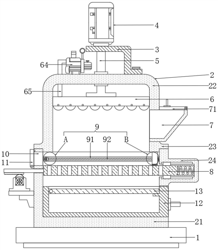
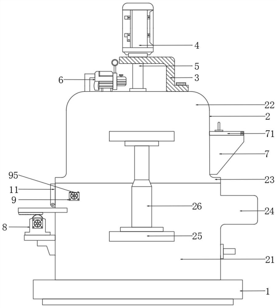
[0029] see Figure 1-6 , the present invention provides a technical solution: a garbage disposal box that facilitates solid-liquid separation of garbage, please refer to figure 1 , comprising a base 1, the base 1 plays the role of a support and installation structure, a treatment box 2 is fixedly arranged on the top of the base 1, and the treatment box 2 is used to process garbage, and the electrical components appearing in the present invention are all connec...


PUM


Abstract

The invention discloses a garbage treatment box facilitating garbage solid-liquid separation, and belongs to the technical field of garbage treatment boxes. The garbage treatment box comprises a base.A treatment box body is fixedly arranged at the top of the base and comprises a bottom box fixed to the top of the base, and a dewatering and drying part is movably arranged in an inner cavity of a top box. A compression supporting plate mechanism matched with the dewatering and drying part is arranged at the top of an inner cavity of the bottom box, and a cleaning pushing structure matched withthe compression supporting plate mechanism is arranged on the inner wall of the rear side of the bottom box. According to the garbage treatment box, under pressing of a pressing roller, part of liquidin garbage is separated out. Through a driving motor, a rotating wheel, an incomplete tooth section, a rack, a movable column, a stress spring and a rubber corrugated pipe, the pressing roller rollsto achieve uniform compression of the garbage, and residual liquid continues to be compressed out. After compression, through an air blower, a heating element, a telescopic hose, a hollow shell and anozzle, the treatment efficiency and quality are greatly improved, secondary treatment is not needed, and the energy consumption and the cost are reduced.

Description

technical field [0001] The invention relates to the technical field of garbage disposal boxes, in particular to a garbage disposal box and a treatment method for facilitating solid-liquid separation of garbage. Background technique [0002] In people's life and work, various garbage will be produced, such as construction waste and kitchen waste, among which kitchen waste is more generated. If these kitchen wastes are directly dumped, it will be waste and cause pollution. However, food waste is often a mixture of a large amount of solid waste and liquid waste. Usually, these wastes need to be separated from solid and liquid before subsequent treatment. [0003] However, the existing solid-liquid separation garbage treatment tanks have the following defects in use: 1. Most of them adopt a simple compression dehydration method, and the dehydration quality is poor, resulting in some liquid still remaining in some garbage, resulting in the need for secondary treatment. Reduced p...

Claims


Application Information

Patent Timeline
IPC IPC(8): B30B9/06B30B9/26B30B15/00B01D29/56B01D29/64B01D29/82B01D29/84B01D29/94
CPCB30B9/06B30B9/26B30B15/0052B01D29/56B01D29/826B01D29/843B01D29/6423B01D29/94
Inventor 赵兴寿
Owner 赵兴寿
Learn More