Eureka AIR delivers breakthrough ideas for toughest innovation challenges, trusted by R&D personnel around the world.

Positioning sighting device

A technology of aimer and positioning rod, which is applied in the field of positioning aimer, can solve the problems of increasing patient pain, increasing the difficulty of surgery, and hitting crooked bone needles, so as to save operation time, reduce anesthesia time, and achieve the effect of precise correspondence

Pending Publication Date: 2020-10-20
花奇凯
View PDF0 Cites 0 Cited by
  • Summary
  • Abstract
  • Description
  • Claims
  • Application Information

AI Technical Summary

Problems solved by technology

The Chinese utility model patent discloses a periosteum transporter, application number: 2020. This type of periosteum transporter can be used not only for the treatment of periosteum transport technology, but also for the place where the microvascular network needs to be reconstructed in the ischemic part. By moving the periosteum To stimulate the growth of blood vessels; however, when using the periosteum mover during the operation, bone needles need to be driven into the bone to support and fix the periosteum support piece, but when the periosteum support piece is placed under the periosteum, the skin and periosteum cover it The hole on the periosteum supporting sheet is opened, and the bone needle is driven into the hole on the periosteum supporting sheet by the doctor's naked eyes, which increases the difficulty of the operation. If the doctor is not careful, the bone needle will be twisted, which increases the pain of the patient.

Method used


Image

  • Positioning sighting device
  • Positioning sighting device
  • Positioning sighting device

Examples


Embodiment 1

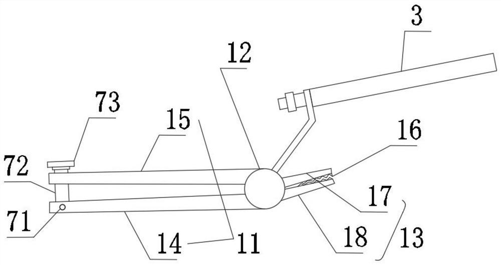
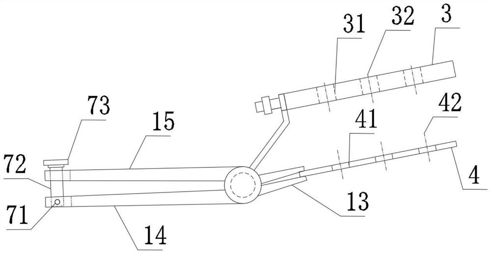
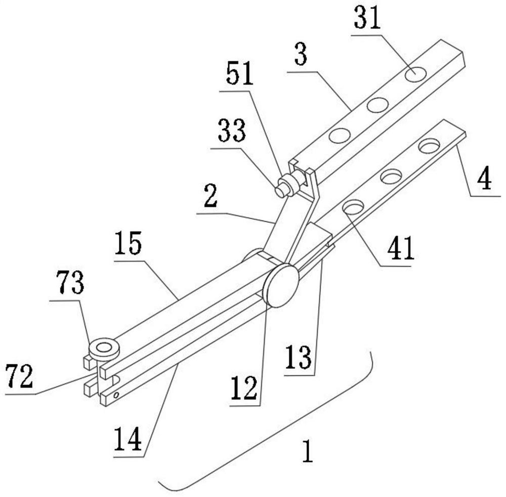
[0031] Such as Figure 1 to Figure 4 As shown, a positioning sight includes a clamping device 1, a connecting rod 2 and a positioning rod 3. The clamping device 1 is used to clamp the periosteal support sheet 4, and one end of the connecting rod 2 is connected to the clamping device 1. The other end is connected to the positioning rod 3, the positioning rod 3 is provided with an aiming hole 31, the center axis 32 of the aiming hole is the same as the center axis 42 of the hole on the periosteal support sheet, the aiming hole 31 is provided with three (see figure 2 ).

[0032] In order to be able to replace different positioning rods 3, the connection between the connecting rod 2 and the positioning rod 3 is set as a detachable connection, and different types of positioning rods 3 can be replaced according to different surgical requirements, so as to adapt to the holes 41 on different periosteal support sheets. s position. The detachable connection is that a screw 33 is provided ...

Embodiment 2

[0045] Such as Figure 5 to Figure 7 As shown, a positioning sight includes a clamping device 1, a connecting rod 2 and a positioning rod 3. The clamping device 1 is used to clamp the periosteal support sheet 4, and one end of the connecting rod 2 is connected to the clamping device 1. The other end is connected to the positioning rod 3, the positioning rod 3 is provided with an aiming hole, the center axis 32 of the aiming hole is the same as the center axis 42 of the hole on the periosteal support sheet, and there are three aiming holes 31.

[0046] In order to be able to replace the different positioning rods 3, the connection between the connecting rod 2 and the positioning rod 3 is set as a detachable connection, and different types of positioning rods 3 can be replaced according to different surgical requirements, so as to adapt to the different holes on the periosteal support sheet. position. A positioning sight further includes a bolt 6 and a second nut 73. The detachabl...


PUM


Abstract

The invention discloses a positioning sighting device and belongs to the technical field of medical instruments. The positioning sighting device is characterized by comprising a clamping device, a connecting rod and a positioning rod, wherein the clamping device is used for clamping a periosteum support piece, one end of the connecting rod is connected with the clamping device, the other end of the connecting rod is connected with the positioning rod, sighting holes are formed in the positioning rod, and the central axis of the sighting holes and the central axis of holes in the periosteum support piece are the same. The positioning sighting device is simple in structure, convenient to operate, low in production cost, high in practicability, capable of quickly positioning the holes in theperiosteum support piece, high in positioning accuracy and high in use stability; the skidding phenomenon of the positioning sighting device during clamping of the periosteum support piece can be greatly reduced by arrangement of antiskid lines on a clamp mouth, a fixing device is arranged on a handle and used for fixing the handle, then the periosteum support piece can be firmly clamped, meanwhile, a doctor does not need to hold the handle with great force during use, shift or sliding of the periosteum support piece due to uneven force application of the doctor is also greatly reduced, and the stability of the positioning sighting device is greatly improved.

Description

Technical field [0001] The invention belongs to the technical field of medical equipment, and specifically relates to a positioning sight. Background technique [0002] Chronic hard-to-heal wounds refer to wounds that have no healing tendency after treatment for at least 1 month. The causes of chronic wounds mainly include metabolic diseases (diabetes), trauma, infections and burns, tumors, and vascular diseases of the lower limbs. Among them, the proportion of diabetes in metabolic diseases has increased year by year. By 2008, the proportion of the causes of chronic wounds investigated in China was as high as 33.3% has become the main cause of chronic refractory wounds. Because in the lifetime of diabetic people, about 25% of patients (prevalence) will develop diabetic foot of varying degrees. Diabetic foot refers to diabetic neuropathy, including peripheral nerve sensory disturbance and autonomic nerve damage, and lower limb vascular disease-arteries Sclerosis causes peripher...

Claims


Application Information

Patent Timeline
IPC IPC(8): A61B17/17A61B17/28
CPCA61B17/17A61B17/28A61B2017/2808
Inventor 赵劲民花奇凯丁毅钟兆伟
Owner 花奇凯
Why Eureka
Eureka Blog
Learn More