
Packaging structure of integrated fuel cell stack and assembling method thereof

A fuel cell stack and packaging structure technology, which is applied in the direction of fuel cells, circuits, electrical components, etc., can solve the problems of large volume and weight, poor cross-sealing effect of sealing surfaces, and difficulty in ensuring assembly tolerances, etc., to achieve volume and weight reduction , strong shock resistance, good insulation effect

Pending Publication Date: 2020-10-16
上海氢晨新能源科技有限公司
View PDF3 Cites 10 Cited by
  • Summary
  • Abstract
  • Description
  • Claims
  • Application Information

AI Technical Summary

Problems solved by technology

[0003] Chinese patent (publication number is CN106450372A) discloses a kind of stack fastening structure with external positioning function: the external positioning block is fastened on the back side of the side packaging plate, and then fastened to the stack. Its disadvantages are: 1 .Split packaging cannot be sealed and cannot meet the protection level standards of automotive fuel cells; 2. The fastening direction of the packaging plate and the end plate of the stack is the normal direction of the stack. After fastening, the positioning block and the stack The assembly tolerance between the sides of the body is difficult to guarantee, so that the positioning of the stack cannot be realized
[0004] Chinese patent (publication number CN103633358A) discloses a highly integrated metal plate fuel cell stack: it discloses a split-type stack packaging structure, and the side packaging plate plays the role of fastening the stack. One-piece packaging cannot achieve sealing, and cannot meet the protection level standards of automotive fuel cells, and the assembly size deviation cannot be guaranteed; on the other hand, there is no positioning structure for the stack on the packaging structure, and the stack will not Very prone to leakage failure due to vibration collapse
[0005] Chinese patent (publication number is CN110098414A) discloses a packaging structure of a fuel cell bipolar plate and a fuel cell stack, which solves the problem of the large number of components in the existing packaging structure, the failure of the stack due to vibration and deformation, and the large number of sealing surfaces Or the technical problem of poor cross-sealing effect of the sealing surface, but the structure is relatively complex, the volume and weight are large, it cannot be adapted to the core structure of different stacking methods, and it is not easy to achieve rapid installation
[0006] Therefore, there is a lack of a fuel cell stack packaging structure with strong shock resistance, good insulation, compact volume and weight, capable of packaging core structures of different stacking methods, and a relatively simple and fast assembly method

Method used


Image

  • Packaging structure of integrated fuel cell stack and assembling method thereof
  • Packaging structure of integrated fuel cell stack and assembling method thereof
  • Packaging structure of integrated fuel cell stack and assembling method thereof

Examples


Embodiment 1

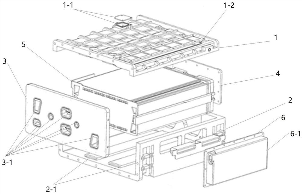
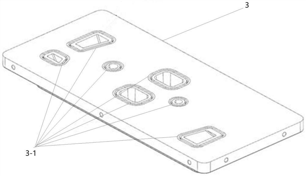
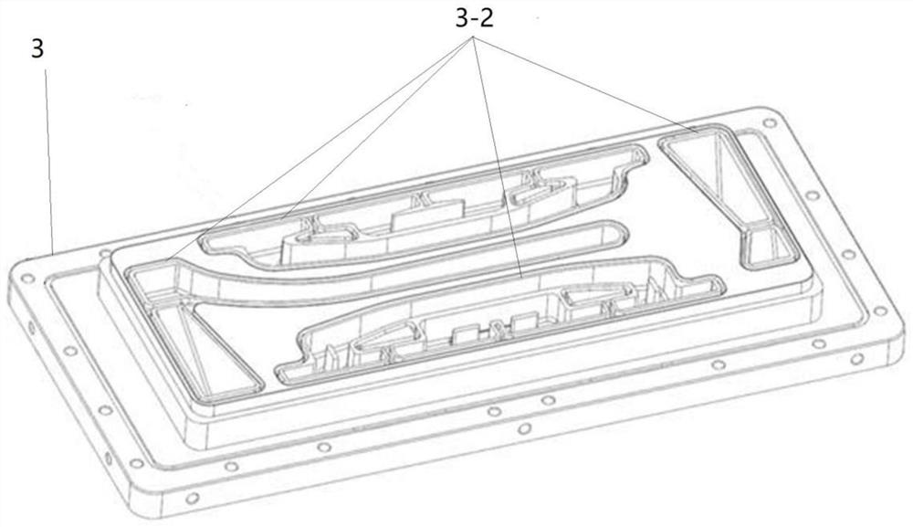
[0055] In a specific embodiment, as shown in the accompanying drawing Figure 1-Figure 8 As shown, a packaging structure of an integrated fuel cell stack includes an upper casing (1), a lower casing (2), a front end plate (3), a rear cover plate (4) and a core structure (5); The front end plate (3) is provided with gas ports (3-1) and flow channel structure (3-2); the front end plate (3) is located directly in front of the core structure (5), and is fixedly connected to the upper shell (1) and the lower shell (2); the upper casing (1) is located directly above the core structure (5), and is fixedly connected with the lower casing (2), the front end plate (3) and the back cover (4); the lower casing (2) is located in the stack directly below the core structure (5); the rear cover plate (4) is located directly behind the core structure (5), and is fixedly connected to the upper shell (1) and the lower shell (2); the core structure (5) is wrapped with insulating Guard plate; the...

Embodiment 2

[0067] In a specific embodiment, as shown in the accompanying drawing Figure 9-10 As shown, the specific steps are:

[0068] S1: Through the pre-positioning of the auxiliary tooling installed on the bottom plate (7-1) of the press, the press (7) needs to have a pressing function, and the upper part of the press (7) has a top plate (7-2) of the press; the press The top plate (7-2) is provided with positioning holes, which are used to locate the six positioning rod assemblies (7-3) used for core assembly and positioning; place the front end plate (3) on the bottom plate of the press (7-1) Inside; pass the positioning rod assembly (7-3) consisting of six positioning rods through the positioning hole of the press top plate (7-2) and the positioning hole of the auxiliary positioning block that is concentric with the corresponding positioning hole; adjust the front plate (3) position, so that it is close to the positioning rod assembly (7-3); according to the six-point positioning...


PUM


Abstract

The invention provides a packaging structure of an integrated fuel cell stack and an assembling method of the packaging structure. The packaging structure of the fuel cell stack comprises a front endplate, an upper shell, a lower shell, a reactor core structure and a rear cover plate; the upper end plate is provided with a common pipeline which is communicated with a reactor core of the electricpile to form a flow channel for providing reaction gas and cooling liquid; and the upper shell and the lower shell are provided with anti-collapse structural components which are tightly attached to the reactor core. According to the packaging structure of the integrated fuel cell stack, the performance of the fuel cell stack is greatly improved, the size and the weight of the fuel cell stack areeffectively reduced, and the overall integration degree of the fuel cell stack is greatly improved; meanwhile, the vibration resistance and the insulativity of the fuel cell stack are further improved. Meanwhile, the integrated packaging structure can achieve rapid assembly and assembly line work.

Description

technical field [0001] The invention relates to the technical field of fuel cell packaging, in particular to a packaging structure of an integrated fuel cell stack and an assembly method thereof. Background technique [0002] The fuel cell stack is formed by end plates that hold and compress on both sides, an insulating spacer, a current exporter, a series of single cells stacked in layers along the normal direction of the single cell reaction surface, and a packaging structure. The electric stack uses hydrogen fuel and air as the reaction gas, and generates electric energy through electrochemical action, which is exported through the current exporter to supply power to the load. When the stack is in use, its structural stability will be affected by vibration and shock on the one hand, and also by itself on the other hand, and because the fuel cell is limited by fuel loading, its volume is generally large. [0003] Chinese patent (publication number is CN106450372A) disclos...

Claims


Application Information

Patent Timeline
Patent Type & Authority Applications(China)
IPC IPC(8): H01M8/2475
CPCH01M8/2475Y02E60/50
Inventor 刘晴晴赵树钊程旌德耿洪泉梁鹏
Owner 上海氢晨新能源科技有限公司
Learn More