Solar dual-source heat pump heat supply system

A dual-source heat pump and solar technology, applied in the field of solar dual-source heat pump energy supply system, can solve the problems of large heating load, large shape coefficient, and high failure rate, so as to increase the heat exchange area, increase the inlet temperature, and improve the COP Effect

Inactive Publication Date: 2020-10-16
山西山能综合能源有限公司
View PDF6 Cites 0 Cited by
  • Summary
  • Abstract
  • Description
  • Claims
  • Application Information

AI Technical Summary

Problems solved by technology

[0002] Conventional coal-to-electricity technology cannot be afforded by the government, power grid, and farmers for a long time due to large government subsidies, high grid capacity expansion costs, and high operating costs for farmers. Large-scale promotion and application in rural areas is not a long-term solution
[0003] In rural areas and old towns, the ambient temperature is low and the heating time is long. At present, most of them are heated by decentralized coal-fired furnaces. Most of the buildings are small single buildings with low building concentration, large shape coefficient, large heating load and high heating temperature (heating The central heating pipe network has high heating investment and large heat loss, the gas pipe network and gas heating supply have high safety risks, and the gas source is insufficient. Real conditions such as peak and valley power policies and financial subsidies need to be matched
The air source heat pump compressor works under the condition of high pressure ratio for a long time, and often operates at the critical point, the failure rate increases, and it is easy to burn the compressor, which greatly increases the maintenance cost
Unable to adapt to extreme cold working conditions below -25°C ambient temperature and high outlet water temperature above 50°C (radiator); in rainy and snowy weather, due to the frequent defrosting of the air source heat pump, the heating load cannot meet the heating demand of the building

Method used


Image

  • Solar dual-source heat pump heat supply system

Examples


Embodiment Construction

[0012] In order to make the technical means, creative features, goals and effects achieved by the present invention easy to understand, the technical solutions in the embodiments of the present invention will be clearly and completely described below in conjunction with the accompanying drawings in the embodiments of the present invention. Obviously, the The described embodiments are only some, not all, embodiments of the present invention. Based on the embodiments of the present invention, all other embodiments obtained by persons of ordinary skill in the art without creative efforts fall within the protection scope of the present invention.

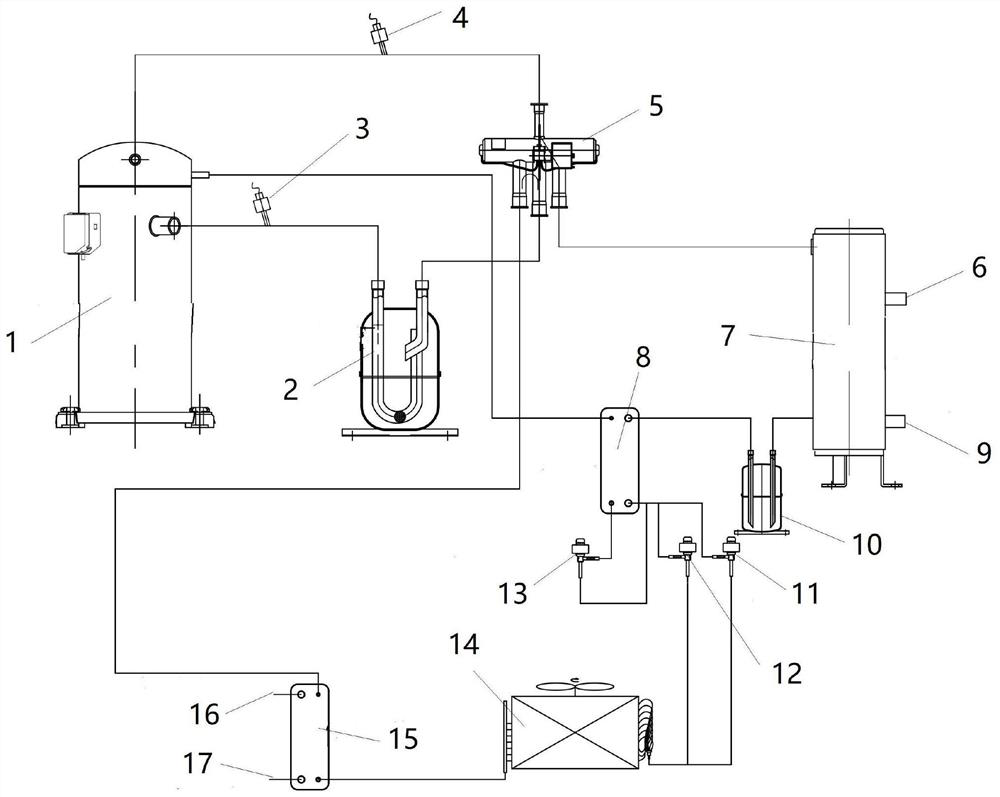
[0013] see figure 1 , figure 1 A solar dual-source heat pump energy supply system is shown, including a heat pump low-temperature enthalpy injection compressor 1, a gas-liquid separator 2, a four-way valve 5, a heating heat exchanger 7, a liquid storage device 10, an economizer 8, and fins Heat exchanger 14, solar panel exchange 15, t...


PUM


Abstract

The invention relates to the technical field of heat supply and heating, in particular to a solar dual-source heat pump heat supply system. The solar dual-source heat pump heat supply system comprisesa heat pump low-temperature spray enthalpy compressor, a gas and liquid separator, a four-way valve, a heating heat exchanger, a liquid storage device, an economizer, a fin heat exchanger, and a solar plate type heat exchanger. The system has the beneficial effects that the solar plate type heat exchanger is added, a low-temperature heat source of a solar heat collecting plate and the low-temperature heat in the air can be provided for the fin heat exchanger, the heat exchange area and the heat exchange amount can be increased, the inlet temperature of the fin heat exchanger and the inlet temperature of the heat pump low-temperature spray enthalpy compressor can be improved, the energy efficiency ratio COP of the heat pump low-temperature spray enthalpy compressor can be greatly improved,and multi-energy mutual complementing of the solar energy ad air energy dual heat source can be achieved. When the direct solar energy is little at night or cloudy sky, the system can still absorb heat from the air environment through the solar heat collecting plate, the heat can be provided for the heat pump low-temperature spray enthalpy compressor, in the all-weather and all process, heat is absorbed and exchanged, and 24-hour continuous energy supply is achieved.

Description

technical field [0001] The invention relates to the technical field of heating and heating, in particular to a solar energy dual-source heat pump energy supply system. Background technique [0002] Conventional coal-to-electricity technology cannot be afforded by the government, power grid, and farmers for a long time due to heavy government subsidies, high grid capacity expansion costs, and high operating costs for farmers. It is not a long-term solution to truly promote and apply it on a large scale in rural areas. [0003] In rural areas and old towns, the ambient temperature is low and the heating time is long. At present, most of them are heated by decentralized coal-fired furnaces. Most of the buildings are small single buildings with low building concentration, large shape coefficient, large heating load and high heating temperature (heating The central heating pipe network has high heating investment and large heat loss, the gas pipe network and gas heating supply ha...

Claims


Application Information

Patent Timeline
IPC IPC(8): F24D15/04F24D15/02F24S20/40F25B30/06
CPCF24D15/02F24D15/04F24D2200/32F25B30/06F24S20/40Y02E10/40
Inventor 何艳山
Owner 山西山能综合能源有限公司
Why Eureka
Try Eureka