Medical artemisia argyi rapid cut-off equipment
A medical and wormwood technology, applied in the field of medical wormwood rapid cutting equipment, can solve the problems of low work efficiency, inconvenient transportation of wormwood, etc., and achieve the effect of reducing labor intensity
- Summary
- Abstract
- Description
- Claims
- Application Information
AI Technical Summary
Problems solved by technology
Method used
Image


Examples
Embodiment 1
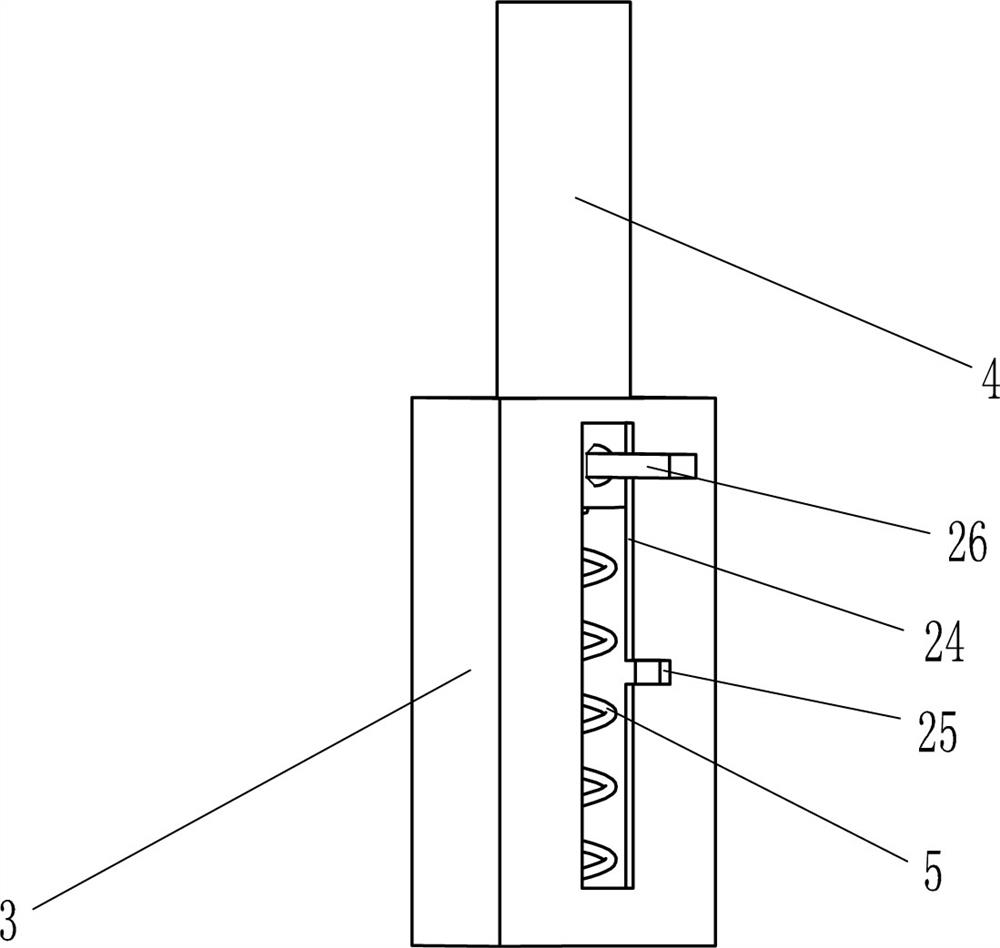
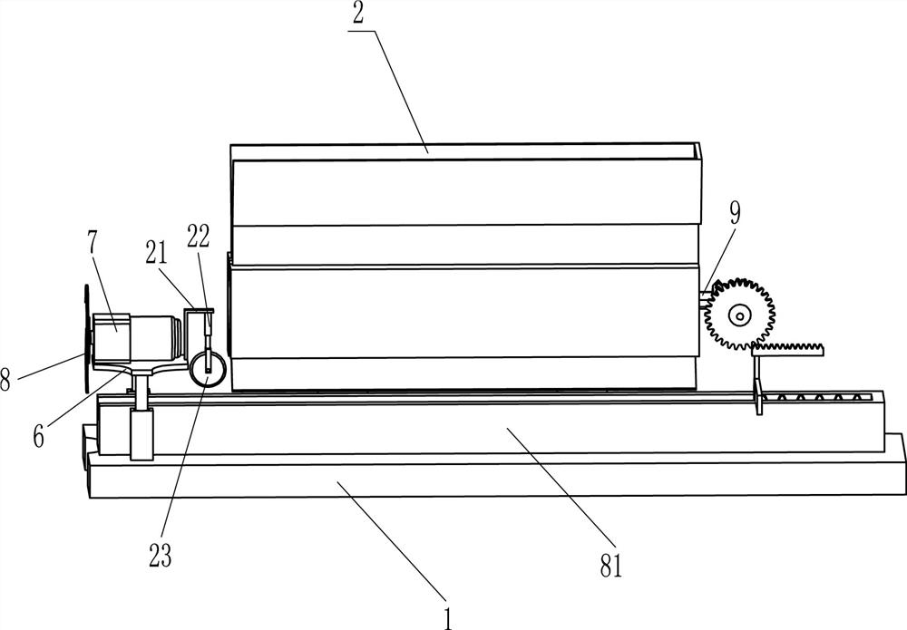
[0025] A kind of fast cut-off device of wormwood for medical use, such as figure 1 , figure 2 and Figure 5 As shown, it includes a bottom plate 1, a blanking mechanism 2, a sliding pipe 3, a sliding rod 4, a first spring 5, a mounting plate 6, a reduction motor 7, a cutting knife 8 and a conveying trough 81, and a blanking mechanism is installed on the bottom plate 1. 2. Two sliding tubes 3 are installed on the bottom plate 1 on the left side of the blanking mechanism 2. A sliding rod 4 is arranged inside the sliding tube 3. A first spring 5 is arranged between the sliding rod 4 and the sliding tube 3. The two sliding rods 4 A mounting plate 6 is welded between the top ends, and the top of the mounting plate 6 is provided with a deceleration motor 7 through bolts, a cutting knife 8 is installed on the output shaft of the deceleration motor 7, and a conveyor is installed on the bottom plate 1 between the two sliding pipes 3. Groove 81, conveying groove 81 is positioned at t...
Embodiment 2
[0030] On the basis of Example 1, such as figure 1 and image 3 Shown, also include rotating rod 9, first bevel gear 10, fixed plate 11, rotating shaft 12, second bevel gear 13, spur gear 14, circular plate 16, second spring 17, moving plate 18, support plate 19 With rack 20, grooved roller 204 right-hand ends are equipped with rotating rod 9, and rotating rod 9 passes the right side wall of placing frame 203, and the right end of rotating rod 9 is equipped with the first bevel gear 10, and the placing frame 203 of rotating rod 9 rear sides A fixed plate 11 is installed on the fixed plate 11, and a rotating shaft 12 is installed on the fixed plate 11. A second bevel gear 13 is installed on the rotating shaft 12. The second bevel gear 13 meshes with the first bevel gear 10. A spur gear 14 is fixed on the front end of the rotating shaft 12. , the sliding type is provided with circular plate 16 in conveying groove 81, is fixedly connected with second spring 17 between the right ...
Embodiment 3
[0033] On the basis of Example 2, such as figure 1 Shown, also comprise L-shaped plate 21, telescoping rod 22 and pinch wheel 23, the mounting plate 6 on the right side of deceleration motor 7 is provided with L-shaped plate 21, and L-shaped plate 21 is provided with telescopic rod 22, and telescopic rod 22 A pinch wheel 23 is installed on it, and the pinch wheel 23 is located directly above the conveying trough 81 .
[0034] Such as Figure 5 As shown, it also includes a clamping rod 26. There is a slot 24 on the rear side wall of the rear sliding tube 3, and a slot 25 is formed on the sliding tube 3 on the left side of the slot 24. The slot 25 is connected to the slot. 24 communicates with each other, and the rear side wall of the rear side slide bar 4 is rotatably provided with a clamping rod 26, and the clamping rod 26 passes through the slot 24.
[0035] The downward movement of the mounting plate 6 can make the L-shaped plate 21 move downward, and the downward movement...
PUM
 Abstract
Description
Claims
Application Information
 - R&D
- Intellectual Property
- Life Sciences
- Materials
- Tech Scout
- Unparalleled Data Quality
- Higher Quality Content
- 60% Fewer Hallucinations
Browse by: Latest US Patents, China's latest patents, Technical Efficacy Thesaurus, Application Domain, Technology Topic, Popular Technical Reports.
© 2025 PatSnap. All rights reserved.Legal|Privacy policy|Modern Slavery Act Transparency Statement|Sitemap|About US| Contact US: help@patsnap.com