Workpiece clamping method using differential pressure type pneumatic clamp
A differential pressure, pneumatic clamping technology, applied in the direction of clamps, manufacturing tools, etc., can solve the problems of unstable clamping, insufficient clamping force, and inability to adjust clamping force, etc., and achieve the effect of reducing insufficient clamping force
- Summary
- Abstract
- Description
- Claims
- Application Information
AI Technical Summary
Problems solved by technology
Method used
Image
Examples
Embodiment 1
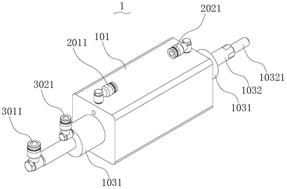
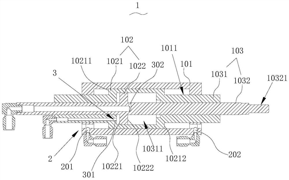
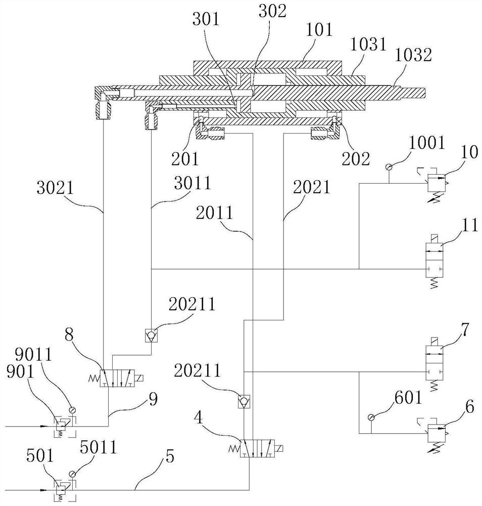
[0065] refer to Figure 1~3 , this embodiment discloses a differential pressure pneumatic telescopic cylinder 1, comprising a cylinder body 101, a piston 102 and a piston rod 103 connected to the piston 102, at least two piston rods 103 are provided, and each piston rod 103 is connected to a piston 102 , the cylinder body 101 is provided with a primary sliding chamber 1011, the piston rod 103 includes a primary telescopic rod 1031 and several secondary telescopic rods 1032, the piston 102 of the primary telescopic rod 1031 slides in the primary sliding chamber 1011, and the primary Telescopic rod 1031, several secondary telescopic rods 1032 are provided with secondary sliding cavity 10311, primary telescopic rod 1031, several secondary telescopic rods 1032 are nested successively, and the piston 102 of secondary telescopic rod 1032 is in the secondary Sliding in the stage sliding chamber 10311;
[0066] In the primary sliding chamber 1011, the piston 102 of the primary telesc...
Embodiment 2
[0078] refer to Figure 4 , this embodiment discloses another differential pressure pneumatic telescopic cylinder 1, based on embodiment 1, the differences between this embodiment and embodiment 2 are:
[0079] In this embodiment, the third ventilation hole 301 and the fourth ventilation hole 302 are both arranged on the primary telescopic rod 1031 , and the third ventilation hole 301 and the fourth ventilation hole 302 are respectively located on two sides of the second plug body 1022 .
[0080] Compared with Embodiment 1, the size of the primary telescopic rod 1031 in the radial direction is larger.
Embodiment 3
[0082] refer to Figure 5-7 , this embodiment discloses a differential pressure pneumatic clamp 12, which includes the differential pressure pneumatic telescopic cylinder 1 of the above embodiment, and also includes a clamp body 1201, a first jaw 1202, a second jaw 1203, a rack and pinion The transmission assembly 1204, the rack and pinion transmission assembly 1204 drives the first jaw 1202 and the second jaw 1203 to move toward each other or move away from each other, the cylinder body 101 of the differential pressure pneumatic telescopic cylinder 1 is fixed to the clamp body 1201, and the differential pressure telescopic The output end 10321 of the cylinder is connected with the first jaw 1202 or the second jaw 1203 , and the moving direction of the output end 10321 is parallel to the moving direction of the first jaw 1202 or the second jaw 1203 .
[0083] refer to Figure 6 , in this embodiment, the rack and pinion transmission assembly 1204 includes a driving gear 12041 ...
PUM
 Abstract
Description
Claims
Application Information
 - Generate Ideas
- Intellectual Property
- Life Sciences
- Materials
- Tech Scout
- Unparalleled Data Quality
- Higher Quality Content
- 60% Fewer Hallucinations
Browse by: Latest US Patents, China's latest patents, Technical Efficacy Thesaurus, Application Domain, Technology Topic, Popular Technical Reports.
© 2025 PatSnap. All rights reserved.Legal|Privacy policy|Modern Slavery Act Transparency Statement|Sitemap|About US| Contact US: help@patsnap.com


