
Scraper type film evaporator

A thin-film evaporator and scraper-type technology, applied in vertical tube evaporators, evaporator accessories, evaporation, etc., can solve the problems of limited application scope, waste, surface expansion, etc., to achieve stable and efficient separation effect, continuous and uniform feeding, Good sealing performance

Pending Publication Date: 2020-10-16
苏州岑途智能装备科技股份有限公司
View PDF0 Cites 1 Cited by
  • Summary
  • Abstract
  • Description
  • Claims
  • Application Information

AI Technical Summary

Problems solved by technology

[0003] The function of the scraper is to thin the material with the inner wall of the cylinder. At present, the feeding method of the material is to directly open the feeding port on the cylinder, so that the scraper can directly thin the material. The area is obvious, and it is impossible to achieve uniform feeding on the feed, which will affect the separation effect of the evaporator
[0004] In addition, the scraper structure currently on the market is mainly a rigid scraper fixed on the rotor. However, in this solution, the distance between the scraper and the cylinder wall is fixed, and the scope of application is limited. However, the material is affected by many factors during the evaporation process. , such as residence time, self-viscosity, etc., and the thickness distribution is different
[0005] Moreover, after some raw materials are processed at the front end and then enter the vacuum heating environment, they are prone to surface expansion, forming air bubbles, escaping from the vacuum pipeline, and generating waste.

Method used


Image

  • Scraper type film evaporator
  • Scraper type film evaporator
  • Scraper type film evaporator

Examples


Embodiment 1

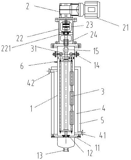
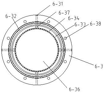
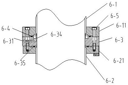
[0032] A scraped film evaporator, such as Figure 1-5 As shown, it includes the evaporator cylinder 1 and the driving structure 2 arranged on the upper side of the evaporator cylinder 1, the scraper cage structure 3 is arranged in the evaporator cylinder 1, the upper side is connected to the driving structure 2, and the lower side is The position is limited by the bearing 12 on the lower head 11 at the bottom of the evaporator cylinder 1 , and the lower side of the lower head 11 is provided with a discharge port 13 .

[0033] In terms of the heat exchange mechanism, the side wall of the evaporator cylinder 1 is provided with a water chamber 4, and the water chamber 4 is provided with a water inlet 41 and a water outlet 42, that is, the heat exchange liquid enters from the bottom and exits from the top.

[0034] The outer side of the water chamber 4 is provided with an insulating layer 5 to ensure a better heat exchange effect.

[0035] The evaporator cylinder 1 is provided wi...


PUM


Abstract

The invention discloses a scraper type film evaporator. The evaporator comprises an evaporator cylinder and a driving structure arranged on the upper side of the evaporator cylinder. The scraper cagestructure is arranged in the evaporator cylinder; the upper side is connected to the driving structure; the lower side is limited by a bearing on a lower seal head at the bottom of the evaporator cylinder; a discharge port is arranged in the lower side of the lower seal head. A water cavity is formed in the side wall of the evaporator cylinder, a water inlet and a water outlet are formed in the lower portion of the water cavity in an up-down mode, a heat preservation layer is arranged on the outer side of the water cavity, a cleaning opening and a vacuum connector are sequentially formed in the cylinder wall, on the upper side of the scraper cage structure, of the evaporator cylinder upwards, and a feeding structure is arranged on the cylinder wall of the evaporator cylinder adjacent to the scraper cage structure. Through the arrangement of the distributing device, materials are evenly fed into the whole cylinder wall in an overflowing mode, discharging is continuous and even, subsequent scraper blade thinning is facilitated, and it is guaranteed that the separation effect of the evaporator is stable and efficient.

Description

technical field [0001] The invention relates to the field of evaporators, in particular to a scraper type thin film evaporator. Background technique [0002] The scraper evaporator thins the material on the inner wall of the evaporator cylinder through the scraper, and efficiently and stably separates the organic solvent or volatile solvent through heat exchange. [0003] The function of the scraper is to thin the material with the inner wall of the cylinder. At present, the feeding method of the material is to directly open the feeding port on the cylinder, so that the scraper can directly thin the material. The area is obvious, and it is impossible to achieve uniform feeding on the feed, which will affect the separation effect of the evaporator. [0004] In addition, the scraper structure currently on the market is mainly a rigid scraper fixed on the rotor. However, in this solution, the distance between the scraper and the cylinder wall is fixed, and the scope of applica...

Claims


Application Information

Patent Timeline
Patent Type & Authority Applications(China)
IPC IPC(8): B01D1/06B01D1/22B01D1/30
CPCB01D1/0064B01D1/065B01D1/30
Inventor 尹磊丁煜
Owner 苏州岑途智能装备科技股份有限公司
Learn More